Excerpt
Contents
ABSTRACT
RESUMEN
Figures
Tables
Chapter 1. Introduction
1.1 CubeSat missions
1.1.1 Poly Picosatellite Orbital Deployer (P-POD)
1.1.2 CubeSat
1.2 Project objectives
Chapter 2. Background
2.1 Missions
2.1.1 NASA Missions
2.1.2 ESA Missions
2.2 Structures
2.2.1 Kit CubeSat Structures
2.2.2 Custom Made CubeSat Structures
2.3 Requirements
2.3.1 Analysis Requirements
Chapter 3. Alternative Cubesat structure
3.1 Introduction and Background
3.2 Additional requirements
3.3 Materials
3.3.1 Metallic materials
3.3.2 Nonmetallic materials
3.3.3 Material evaluation
3.4 Manufacture processes
3.4.1 Metallic Materials:
3.4.2 Non-Metallic Materials
3.4.3 Joint Methods
3.5 Conceptual Study
3.6 Design Concept
3.6.1 Internal Columns
3.6.2 Shear panels
3.6.3 Shear angles
3.6.4 Rails
3.6.5 Feet Blocks
3.6.6 Assembly process
3.6.7 Payload interface
3.7 Finite Element Model
3.7.1 Finite element validation
3.7.2 Load Cases
3.7.3 Static Analysis
3.7.4 Vibration Analysis
3.8 Summary Results
Chapter 4. Conclusions and Future works
APPENDIX A
APPENDIX B
APPENDIX C
REFERENCES
Figures
Figure 1 – AAU Cubesat
Figure 2 – Poly Picosatellite Orbital Deployer P-POD.
Figure 3 – Poly Picosatellite Orbital Deployer (P-POD) cross section.
Figure 4 – P-POD and with its three CubeSats (TacSat-3 Mission)
Figure 5 – 1U Cubesat Specification
Figure 6 – CubeSat Kit Assembly example with skeleton.
Figure 7 – Solid- Wall and Skeletonized assembled CubeSat Kit
Figure 8 – ISIS CubeSat Structure.
Figure 9 – M-Cubed structure and final assembly.
Figure 10 - M-cubed final assembly schematics.
Figure 11 – AubieSat-1 Assembly
Figure 12 – AubieSat-1 Structure Detail.
Figure 13 – IPEX Hypercube Structure
Figure 14 – Cape II Structure
Figure 15 – Fox 1 circuit stack-up / External Structure.
Figure 16 – Forming; Sheet metal bending with V die
Figure 17 – Forming; Edge bending with wiping die
Figure 18 – Forming; Rotary bending of sheet metal
Figure 19 – Forming; Air bending
Figure 20 – Forming; Channel bending
Figure 21 – Forming; U bending
Figure 22 – Forming; Offset bending
Figure 23 – Forming; Stretch bending
Figure 24 – Forming; Draw bending
Figure 25 – Forming; Compression bending
Figure 26 - Machining; Turning Boring
Figure 27 - Machining; Grooving thread cutting
Figure 28 - Machining; end milling face milling
Figure 29 - Machining; drilling counter boring
Figure 30 - Machining; Reaming tapping
Figure 31 – 3D printing
Figure 32 – Inkjet printing
Figure 33 – Jetted Photopolymer
Figure 34 – Vacuum bagging autoclave moulding
Figure 35 – Alternative Structural design - global view
Figure 36 – Alternative Structural Design – Internal Columns
Figure 37 – Alternative Structural Design – Lateral Shear Panels
Figure 38 – Alternative Structural Design – Lateral Access Panel
Figure 39 – Alternative Structural Design – Superior and Lower Shear Panels
Figure 40 – Alternative Structural Design – Antennas deployment
Figure 41 – Alternative Structural Design – Shear Angles
Figure 42 – Alternative Structural Design – Rails
Figure 43 – Alternative Structural Design – Feet Blocks
Figure 44 – Single Point Attachment or Mounting Block
Figure 45 – Plastic Card guide
Figure 46 – Mount clips
Figure 47 – HPA – Single card arrangement
Figure 48 – HPA – Back attachment
Figure 49 – HPA – Forward attachment
Figure 50 – FEM Validation – Composite Boundary
Figure 51 – FEM Validation – Metallic Boundary
Figure 52 – FEM Validation – Angle Normals
Figure 53 – FEM Validation – Column Normals
Figure 54 – FEM Validation – Rail Normals
Figure 55 – FEM Validation – Panel Normals
Figure 56 – FEM Validation – Composite Duplicates Elements
Figure 57 – FEM Validation – Metallic Duplicates Elements
Figure 58 – FEM Validation – Center of Mass and Principal Axis
Figure 59 – Load Cases – Inertial Forces
Figure 60 – Load Cases – Launch Phases
Figure 61 – Load Cases – Load Direction per Launch Phases
Figure 62 – Displacement Results
Figure 63 – Strength Metallic - Stress Maximum Principal
Figure 64 – Strength Metallic - Stress Minimum Principal
Figure 65 – Strength Composite - Strains Maximum Principal
Figure 66 – Strength Composite - Strains Minimum Principal
Figure 67 – Strength Composite - Strains Shear
Figure 68 – Vibration Analysis – Rigid Response
Figure 69 – Vibration Analysis – Elastic Response Boundary Conditions (Feet)
Figure 70 – Vibration Analysis – Elastic Response Boundary Conditions (Y Faces)
Figure 71 – Vibration Analysis – Elastic Response Boundary Conditions (X Faces)
Tables
Table 1 – NASA missions selected on 2010
Table 2 – NASA missions selected on 2011
Table 3 – NASA missions selected on 2012
Table 4 – NASA missions selected on 2013
Table 5 – ESA missions selected on 2007
Table 6 – ESA missions selected on 2013
Table 7– CubeSat Kit Structure Specification
Table 8– ISIS CubeSat Structure specification
Table 9 – General Requirements
Table 10 – Electrical Requirement
Table 11 – Operational Requirement
Table 12 – Mechanical Requirement
Table 13 – Testing Requirement
Table 14 – Analysis Margin Requirements
Table 15 – Analysis and Test requirements.
Table 16 – Aluminum 2024 Mechanical properties
Table 17 - Aluminum 5005 Mechanical properties
Table 18 - Aluminum 5052 Mechanical properties
Table 19 - Aluminum 6061 Mechanical properties
Table 20 - Aluminum 7075 Mechanical properties
Table 21 - Titanium Mechanical properties
Table 22 – Heat resistant alloy Mechanical properties
Table 23 – Composite matrix applications
Table 24 – Composite reinforcement applications
Table 25 – Carbon fiber Mechanical properties
Table 26 – Digital ABS made of RGD515 RGD535 Mechanical properties
Table 27 – Digital ABS RGD525 high (temperature Material) Mechanical properties
Table 28 – Materials criteria evaluation
Table 29 - Materials Evaluation
Table 30 – Adhesive types and applications
Table 31 – Fastening types and applications
Table 32 – TLV-10 Single Shear Allowable for 7075-T6
Table 33 – TLV-10 Bearing Allowable
Table 34 – FEM Validation – CQUAD Elements
Table 35 – FEM Validation – Scalar Properties with added mass
Table 36 – FEM Validation – Center of Gravity Position with added mass
Table 37 – FEM Validation – Scalar Properties
Table 38 – FEM Validation – Center of Gravity Position
Table 39 – FEM Validation – Load Case Legend
Table 40 – Displacement Results
Table 41 – Strength Metallic - Stress Maximum Principal
Table 42 – Strength Metallic - Stress Minimum Principal
Table 43 – Strength Composite - Strains Maximum Principal
Table 44 – Strength Composite - Strains Minimum Principal
Table 45 – Strength Composite - Strains Shear
Table 46 – Riveting Analysis – Shear analysis
Table 47 – Unfolding Analysis – Fiber Strain Criteria
Table 48 – Unfolding Analysis – Hoffman analysis
Table 49 – Result Summary
Table 50 – Strength analysis, - results
Table 51 – Additional analysis - results
Table 52 – APE C – Aluminum minimum bend radius
Table 53 – APE C – Sheet metal gauge versus metal thickness
Chapter 1. Introduction
The CubeSat Project (www.cubesat.org) was developed by California Polytechnic State University, San Luis Obispo and Stanford University's Space Systems Development Lab. The CubeSat program creates launch opportunities for universities previously unable to access space.
Space exploration and research is one of the main purposes of the Aerospace engineering. However, until recent years this experience was banned for students due to the complexity of the work involved, infrequent missions and cost, leaving all that to their professional careers.
1.1 CubeSat missions
The CubeSat reference design was proposed in 1999 by professors Jordi Puig-Suari of California Polytechnic State University (Cal Poly) and Bob Twiggs of Stanford University (Stanford Space Sciences Group). The goal was to enable graduate students to be able to design, build, test and operate in space a spacecraft with capabilities similar to that of the first spacecraft, Sputnik. The CubeSat as initially proposed did not set out to become a standard; rather, it became a standard over time by a process of emergence. The first CubeSats were launched in June 2003 on a Russian Eurockot. (Wikipedia)
illustration not visible in this excerpt
Figure 1 – AAU Cubesat
Source: Aalborg University [http://www.space.aau.dk/cubesat/pictures/AAUcubesat.jpg]
A CubeSat is a 10 cm cube with a mass of up to 1.33 kg with its primary purpose is to provide access to space for small payloads. In order to does that, Cal Poly develop the Poly Picosatellite Orbital Deployer (P-POD) to ensure the security of the primary payload, launch vehicle (LV) and other CubeSats during launch.
All CubeSat that are part of the launch must ensure the safe operation of their system meeting design guidelines and minimum testing requirements.
1.1.1 Poly Picosatellite Orbital Deployer (P-POD)
The Poly Picosatellite Orbital Deployer (P-POD) is the standardization of the Cal Poly for the interface of the CubeSat with the launch vehicle. The P-POD is a rectangular box with a door and a spring mechanism. Once the release mechanism of the P-POD is actuated by a deployment signal sent from the Launch Vehicle (LV), a set of torsion springs at the door hinge force the door open and the CubeSats are deployed by the main spring gliding on its rails and the P-PODs rails. The P-POD is made up of anodized aluminum. CubeSats slide along a series of rails during ejection into orbit CubeSats will be compatible with the P-POD to ensure safety and success of the mission by meeting the dimensions requirements. (Cal Poly).
illustration not visible in this excerpt
Figure 2 – Poly Picosatellite Orbital Deployer P-POD.
Source: Cal-Poly. Design Specification. [http://www.cubesat.org/index.php/documents/developers]
illustration not visible in this excerpt
Figure 3 – Poly Picosatellite Orbital Deployer (P-POD) cross section.
Source: Cal-Poly. Design Specification. [http://www.cubesat.org/index.php/documents/developers]
1.1.2 CubeSat
The CubeSat is a standardized Picosatellite. The basic CubeSat unit consists on a 10 cm cube with a mass of up to 1.33 kg, 1U (Cal Poly). Due to the demand, bigger CubeSat that allow additional payload and versatility are introduced. These additional design are 1.5U, 2U, 3U and +3U. These Picosatellite are going to be out of the scope of this project even when their study could be extrapolated.
During launch stages, the CubeSats are into the P-POD, each P-POD holds three units (1U). For a case where the CubeSats are larger than a standard P-POD, customize P-POD are required.
illustration not visible in this excerpt
Figure 4 – P-POD and with its three CubeSats (TacSat-3 Mission)
Source: EOPortal.org [https://directory.eoportal.org/web/eoportal/satellite-missions/a/aerocube-3]
illustration not visible in this excerpt
Figure 5 – 1U Cubesat Specification
Source: Cal-Poly. Design Specification. [http://www.cubesat.org/index.php/documents/developers]
1.2 Project objectives
The primary objective of this project is to design a new alternative structure concept that can support all the launch and operational loads meeting the general requirements of the Cal Poly. These requirements establish a baseline for the design of a 1U CubeSat, which could safely transport the payload during the whole life of the program.
The general requirements for this project were:
Meet dimensions requirements (interface).
Meet weight distribution requirements.
Material requirements (NASA).
Meet basic static test requirements.
Meet basic vibration test requirements.
The goal of the project is create a new advance alternative structure concept that can meet all the additional requirements:
Light-Weight structure
Multi configurable structure, unique structure for multiple missions.
Use of new materials and processes.
Low manufacture cost
Additional static load cases to ensure optimum payload safely.
Chapter 2. Background
A CubeSat is divided in subsystems, depends on the mission these subsystems will be different, but every Cubesat has to have minimum the following subsystems:
Structure system; the purpose is maintain the integrity of the Cubesat with a mass optimization to support loads up to 10 G’s and provide easy access to all other subsystems.
Power Subsystem; the purpose is produce, store, manage and distribute power to the systems that need it. (Solar arrays, batteries…)
Telemetry Subsystem; The main objective is to transmit the data from the onboard stored data to the ground station
The objective of the current project is the analysis and development of a new solution of the structure system.
2.1 Missions
The two main spaces agencies, NASA and ESA, are the sponsors of the educational oriented CubeSat program. NASA with the CubeSat Launch Initiative (CSLI) program was the pioneer of the student oriented launch program. Before that, Universities had to find sponsor to cover the cost of the launches. These launches typically take place in Russia due mainly to the cost. In the year 2007 the ESA CubeSat program began and 7 CubeSat launched were made up to this date.
These Educational oriented programs provide free launches to any of the selected participants that meet the Cal Poly requirements, plus the specifics for the launch vehicle.
The current project is focus on 1U CubeSat, even when the new standard allows bigger configurations. The reason is because the 1U is the basic unit and due to the technologic demonstration orientation of the CubeSat program.
2.1.1 NASA Missions
In the following tables, it can be found the CubeSat selected for the CubeSat Launch Initiative (CSLI) program every year for the 1U configurations and the structure used. (NASA).
illustration not visible in this excerpt
Table 1 – NASA missions selected on 2010
Source: NASA [http://www.nasa.gov/directorates/heo/home/CSLI_selections.html#2010]
illustration not visible in this excerpt
Table 2 – NASA missions selected on 2011
Source: NASA [http://www.nasa.gov/directorates/heo/home/CSLI_selections.html#2011]
illustration not visible in this excerpt
Table 3 – NASA missions selected on 2012
Source: NASA [http://www.nasa.gov/directorates/heo/home/CSLI_selections.html#2012]
illustration not visible in this excerpt
Table 4 – NASA missions selected on 2013
Source: NASA [http://www.nasa.gov/directorates/heo/home/CSLI_selections.html#2013]
2.1.2 ESA Missions
ESA program is younger and has already a success launch. The selection was made on 2007 and developed of the CubeSat started on 2008 until launch on February 2012.
illustration not visible in this excerpt
Table 5 – ESA missions selected on 2007
Source: ESA [http://www.esa.int/Our_Activities/Launchers/Launch_vehicles/Vega3/CubeSats]
illustration not visible in this excerpt
Table 6 – ESA missions selected on 2013
Source: ESA [http://www.esa.int/Education/ESA_and_student_teams_kick-off_Fly_Your_Satellite]
2.2 Structures
The CubeSat program was initiated at the year 2000. During this time different design trends were study, with the main drive of the design focus on low price, low mass, simple design and ability to support deployable components.
In the next sections there is a study of the trends:
2.2.1 Kit CubeSat Structures
A big percentage of the launched CubeSat uses a purchased CubeSat structure supplied by one of the two main CubeSat manufactures. These structures are supplied in set and must be assemble by the developer.
Pumpkin Incorporated (San Francisco, CA)
This company offers the CubeSat Kit to developers which kit, contains all component necessary to assembly a complete CubeSat in a short time.
illustration not visible in this excerpt
Figure 6 – CubeSat Kit Assembly example with skeleton.
Source: EOPortal.org [https://directory.eoportal.org/documents/163813/200148/OUFTI1_AutoB]
The offered structure meets the following requirements:
illustration not visible in this excerpt
Table 7– CubeSat Kit Structure Specification
Source: cubesatkit.com [http://cubesatkit.com/content/structure.html]
illustration not visible in this excerpt
Figure 7 – Solid- Wall and Skeletonized assembled CubeSat Kit
Source: cubesatkit.com. Overview of the CubeSat kit [http://cubesatkit.com/content/showcase/presentations.html]
Innovative Solutions in Space (ISIS) (Delft, Netherlands)
ISIS mission is to provide low-cost spacecraft and short-turnaround times for mission and application implementation by use of nanosatellites and small microsatellites, with singular emphasis on the design and development of subsystems.
The CubeSat structural design from ISIS is simpler that its competitor. It is compose by two layers of structures:
- Primary Structure: consist of two modular side frames connected with four ribs, joint together with M2.5X6 screws.
- Secondary Structure: it is stack up circuit board system in order to enhance the integrity of the satellite.
We can spot the first design problem, use the circuit board for structural integrity make us risk out payload and subsystems and with that the whole mission.
illustration not visible in this excerpt
Figure 8 – ISIS CubeSat Structure.
Source: ISIS – Innovative Solution in Space [http://www.cubesatshop.com/index.php?page=shop.product_detailsflypage=flypage.tplproduct_id=1category_id=1option=com_virtuemartItemid=66]
illustration not visible in this excerpt
Table 8– ISIS CubeSat Structure specification
Source: ISIS – Innovative Solution in Space [http://www.isispace.nl/brochures/ISIS_CubeSat%20Structures_Brochure_v.7.11.pdf ]
2.2.2 Custom Made CubeSat Structures
The use of Kit Cube Sat structures are used to limit the budget impact, reduce development time and get a structure fabricated with high manufacture capability company. But sometimes, some mission need to fabricate their own in order to try reduce development cost or simply because they need a suitable specific structure for their specific mission.
Next there are some of the custom designs:
M-Cubed
The Michigan Multipurpose Minisat used an in-house machined structure in order to create a suitable bus for all components. The structure also must handle physical interfaces between components, ensuring that any cables are routed correctly within the structure. (Michigan Mutipurpose Minisat)
The main structure is composed of six rectangular isogrid panels attached to four rails at each corner. The isogrid corner panel provides rigidity while being lower in mass than a solid panel. The reduction on weight of the panels allows accessibility to the systems.
The rails to which these panels are attached are hollowed to reduce mass and provide power and electrical access to the spring-loaded plunger necessary to indicate M-cubed is released form the P-POD.
illustration not visible in this excerpt
Figure 9 – M-Cubed structure and final assembly.
Source: University of Michigan [http://umcubed.org/]
illustration not visible in this excerpt
Figure 10 - M-cubed final assembly schematics.
Source: University of Michigan [http://umcubed.org/]
AubieSat-1
Auburn university student space program manufacture the whole CubeSat in house. For the structure subsystem, it used a combination of the circuit boards stack up and everything protected by 6 machine panels similar to the ISIS structure kit. The panels are joining together in each panel corner by one countersink crew.
illustration not visible in this excerpt
Figure 11 – AubieSat-1 Assembly
Source: Auburn University [http://www.space.auburn.edu/ ]
illustration not visible in this excerpt
Figure 12 – AubieSat-1 Structure Detail.
Source: Auburn University [http://www.space.auburn.edu/]
CP8 (IPEX)
The mission of IPEX is to demonstrate operation of autonomous instrument processing, downlink operations, and ground station operation, utilizing the space cube mini payload processing unit to validate a reduction in data product downlink.
The structure is named Hypercube, is a modular design machined specially to hold de cameras and the modular system “Space Cube Mini Mounting”. It is fabricated in 6061 Aluminum. (Cal Poly)
illustration not visible in this excerpt
Figure 13 – IPEX Hypercube Structure
Source: Cal-Poly [http://polysat.calpoly.edu/launched-missions/cp8-ipex/]
Cape -2
The Cape 2 is a communication satellite. The structure subsystem is machined in 2 square frames and 4 columns. This configuration is unique for mission, because the location of the circuit board cannot be configurable.
illustration not visible in this excerpt
Figure 14 – Cape II Structure
Source: University of Louisiana [http://ulcape.org/projects/cubesats/]
Fox-1
This CubeSat failed in 2011, the structure is based in the ISIS structure kit. Composed by an internal circuit stack-up and everything cover by bended sheet metal.
illustration not visible in this excerpt
Figure 15 – Fox 1 circuit stack-up / External Structure.
Source: AMSAT-UK [www.amsat.org/amsat-new/fox/Fox_1_Mechanical-KF4KSS.pp]
PrintSat
The PrintSat is a Picosatellite in progress that using nano-carbon-impregnated plastic using a 3D printer.
Additive manufacturing (also called 3-D printing) has evolved in the past few years to be a very inexpensive and fast way to make mechanical parts. With PrintSat, the entire structure of the small satellite will be printed.
2.3 Requirements
The structure has to meet the requirements specified from Cal Poly for launch vehicle integration. The requirements that are directly or indirect applicable to the structure can be divided as follow:
illustration not visible in this excerpt
Table 9 – General Requirements
Source: Cal-Poly. Design Specification. [http://www.cubesat.org/index.php/documents/developers]
illustration not visible in this excerpt
Table 10 – Electrical Requirement
Source: Cal-Poly. Design Specification. [http://www.cubesat.org/index.php/documents/developers]
illustration not visible in this excerpt
Table 11 – Operational Requirement
Source: Cal-Poly. Design Specification. [http://www.cubesat.org/index.php/documents/developers]
illustration not visible in this excerpt
Table 12 – Mechanical Requirement
Source: Cal-Poly. Design Specification. [http://www.cubesat.org/index.php/documents/developers]
illustration not visible in this excerpt
Table 13 – Testing Requirement
Source: Cal-Poly. Design Specification. [http://www.cubesat.org/index.php/documents/developers]
2.3.1 Analysis Requirements
All analysis requirements are extracted from General environmental verification standard for GSFS payloads, subsystems and components [GSFC-STD-7000].
illustration not visible in this excerpt
Table 14 – Analysis Margin Requirements
Source: GFC-TD-7000
illustration not visible in this excerpt
Table 15 – Analysis and Test requirements.
Source: GFC-TD-7000
Chapter 3. Alternative Cubesat structure
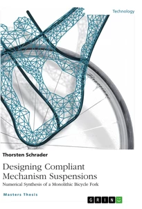
The main purpose of this project is design a 1U CubeSat with an advance technology proving a structure, which meets all the standard requirements in order to provide a structure alternative.
3.1 Introduction and Background
1U CubeSat is an approximate 10 cm side cube, with an approximate mass of 1.33 Kg designed to carry a particular payload. All CubeSat has to meet the requirements stated by Cal poly described in section 2.3.
The Cubesat missions been deployed since 2000, several structure configuration has been studied and optimized. The mission of this project is research all of the previous design and analyze the design for future application on a CubeSat mission.
In order to achieve this mission, additional requirements will be imposed and every aspect of the design will be analyzed.
3.2 Additional requirements
The design CubeSat has to meet the following requirements:
Cost: The Cubesat projects are university projects privately finance, and then investors required minimize the cost: materials, fabrication, components…
Innovative: The Cubesat has to be innovative, educational, scientific interest and technology challenge in order to be selected in a Cubesat program initiative.
Configurable: The design of the Cubesat structure needs to be configurable in order to adequate any possible mission of the future structure with minor modifications.
Weight: the weight of the structure has to be optimized in order to allow the maximum payload.
Thermal protection: In addition to provide a rigid support and protection, the structure also provides thermal protection.
Static load: typically a normal CubeSat is analyzed for 10 g static load, the higher allowable load analyzed shows a 21g allowable load. Our CubeSat will meet the higher requirements with a 25g static load analysis.
Temperature: the temperature analysis will be in the range from -55 Celsius degree up to +90 Celsius degrees.
Vibration: Vibration analysis has to ensure that the structure is far from 10 g rms. Fc 10 g rms.
Deformation: this aspect is not analyzed, but in order to protect our payload, we need to ensure that no load or preload will be created in our circuits boards, payload etc.. Maximum displacement requirement will be 0.5 mm.
Outgassing and Total material Lost (TML): All materials have to meet the outgassing and maximum TML of 1%.
[...]
- Quote paper
- Gustavo Cotta Vallina (Author), 2014, Alternative structure design for Cubesat, Munich, GRIN Verlag, https://www.grin.com/document/284992
Similar texts


Publish now - it's free


Comments