Excerpt
TABLE OF CONTENTS
Dedication
Thesis Approval
Abstract
Acknowledgements
List of Figures
List of Tables
List of Symbols and Abbreviations
CHAPTER 1 Research Curriculum
1.1 General
1.2 Problem Statement and its Significance
1.3 Objectives and Specific Aims
1.4 Scope of the Work and Limitations
1.5 Duration and Place of this Research
1.6 Thesis Organization
CHAPTER 2 Literature Review
2.1 Introduction
2.2 Response Analysis of Granular Soils
2.2.1 Time-dependent behavior
2.2.2 Laboratory studies on particle breakage and constitutive modeling of grain crushing
2.2.3 Effects of water on mechanical response of granular soils
2.3 Geotechnical Engineering and Geology
2.3.1 The geotechnics of crushed soft rocks
2.3.2 Modeling of weathering-induced degradation of soft rocks
2.4 Other Concerns in Geotechnical Engineering
2.5 Concluding Remarks
CHAPTER 3 Experimental Setup
3.1 Introduction
3.2 Background of Hollow Cylinder Devices
3.3 Advantages of Torsional Shear
3.4 General Description of the Apparatus
3.4.1 The hollow torsional cell
3.4.2 Loading system
3.4.3 Measuring system
3.5 Stress and Strain Components in Hollow Cylindrical Specimens
3.5.1 Stress components
3.5.2 Correction of stress components for membrane forces
3.5.3 Calculation of principal stresses
3.5.4 Strain components
3.5.5 Summary of stress-strain formulation in hollow cylinders
3.6 Calibration of Loading and Measuring Systems
3.7 Torsional Shear Test Procedure
3.7.1 Materials
3.7.2 Sample preparation method
3.7.3 HCTS test steps
3.8 Summary
CHAPTER 4 Materials and Methodology
4.1 General
4.2 Materials
4.2.1 Sampling sites
4.2.2 Material preparation
4.2.3 Physical properties of test materials
4.2.4 Quantification of particle disintegration
4.3 Choice of the Apparatus
4.4 Research Methodology
4.4.1 Experimental program
4.4.2 General experimental procedure and stress paths
4.5 Definition of Various Terms
4.6 Summary
CHAPTER 5 Experimental Phase - I: Monotonic Torsional Shear
5.1 Introduction
5.2 Parameters for Comparison of Test Results
5.3 Illustration of Test Conditions
5.4 Experimental Results on Toyoura Sand
5.4.1 Consolidation behavior of TS specimens
5.4.2 Monotonic torsional shear response of TS specimens
5.4.3 Failure envelopes of TS specimens
5.4.4 Shear banding and failure mode of TS specimens
5.5 Test Results on Crushed Sandy Mudstone - HB
5.5.1 Saturation response of HB specimens
5.5.2 Consolidation behavior of HB specimens
5.5.3 Stress-strain and volume-change response of HB specimens
5.5.4 Failure envelopes of HB specimens
5.5.5 Deterioration of soil grains of HB specimens
5.5.6 Shear banding and failure mode of HB specimens
5.6 Test Results on Crushed Massive Mudstone - DS
5.6.1 Saturation response of DS specimens
5.6.2 Consolidation behavior of DS specimens
5.6.3 Stress-strain and volume-change response of DS specimens
5.6.4 Failure envelopes of DS specimens
5.6.5 Deterioration of soil grains of DS specimens
5.6.6 Shear banding and failure mode of DS specimens
5.7 Test Results on Crushed Dolomitic Limestone - GN
5.7.1 Saturation response of GN specimens
5.7.2 Consolidation behavior of GN specimens
5.7.3 Stress-strain and volume-change response of GN specimens
5.7.4 Failure envelopes of GN specimens
5.7.5 Deterioration of soil grains of GN specimens
5.7.6 Shear banding and failure mode of GN specimens
5.8 Test Results on Crushed Sandy Mudstone - YK01
5.8.1 Saturation response of YK01 specimens
5.8.2 Consolidation behavior of YK01 specimens
5.8.3 Stress-strain and volume-change response of YK01 specimens
5.8.4 Failure envelopes of YK01 specimens
5.8.5 Deterioration of soil grains of YK01 specimens
5.8.6 Shear banding and failure mode of YK01 specimens
5.9 Test Results on Crushed Massive Mudstone - YK02
5.9.1 Saturation response of YK02 specimens
5.9.2 Consolidation behavior of YK02 specimens
5.9.3 Stress-strain and volume-change response of YK02 specimens
5.9.4 Failure envelopes of YK02 specimens
5.9.5 Deterioration of soil grains of YK02 specimens
5.9.6 Shear banding and failure mode of YK02 specimens
5.10 Summary of the Test Results
5.11 Concluding Remarks
CHAPTER 6 Experimental Phase - II: Cyclic Torsional Shear
6.1 Introduction
6.2 Experimental Program and Test Conditions
6.3 Cyclic Torsional Shear Tests on Toyoura Sand
6.3.1 Loading history
6.3.2 Consolidation history of TS specimens
6.3.3 Cyclic shear response of TS specimens under Ko=1.0
6.3.4 Cyclic shear response of TS specimens under Ko=0.5
6.4 Cyclic Torsional Shear Tests on Crushed Mudstone
6.4.1 Loading history
6.4.2 Consolidation history of DS specimens
6.4.3 Cyclic shear response of DS specimens under Ko=1.0
6.4.4 Cyclic shear response of DS specimens under Ko=0.5
6.4.5 Effects of cyclic loading on deterioration of soil grains
6.5 Summary
CHAPTER 7 Data Analysis and Interpretation
7.1 General
7.2 Analysis of the Results from Experimental Phase - I
7.2.1 Mechanism of water-induced deterioration
7.2.2 Effects of mineral type on saturation response
7.2.3 Effects of disintegration on particle shape
7.2.4 Quantification of deterioration of soil grains
7.2.5 Degradation index and conventional slake durability test
7.2.6 Correlations of degradation index with consolidation response
7.2.7 Correlations of degradation index with mechanical properties
7.3 Analysis of Results from Experimental Phase - II
7.3.1 Deterioration of soil grains under cyclic loading
7.3.2 Dynamic properties of soils undergoing deterioraion of grains
7.3.3 Volume-change response of crushed rocks to cyclic loading
7.4 Summary
CHAPTER 8 Conclusions and Recommendations
8.1 General
8.2 Conclusions
8.3 Recommendations for Future Research
REFERENCES
APPENDIX: X-Ray Diffraction Analysis
ABSTRACT
With growing infrastructure developments in hilly areas and due to economical constraints of using locally available rockfill materials for construction of embankments, practicing engineers must be acquainted with geotechnical response of non-conventional granular soils. These materials are most likely to disintegrate with time due to physical and chemical weathering. In general, the laboratory investigations on durability characteristics of such materials are only made through simple slaking tests. However, studies examining the effects of slaking-induced disintegration of soil grains on the geotechnical engineering analysis and design parameters are rather limited. This is essentially due to the reason that the grains of standard laboratory sands are mostly durable and hence, the stress-strain response is considered to be unaffected by the presence of water.
In order to explore the possible effects of deterioration of soil grains on static and dynamic properties of granular soils, a series of consolidated drained torsional shear tests on various crushed soft rocks were performed under saturated and dry conditions and compared with a well reported Toyoura silica sand consisting of durable grains. Due to the sensitivity of crushed rockfill to deteriorate upon water-submergence, test under dry conditions represented the response of a soil with intact grains, whereas a similar test under saturated condition simulated the potential reduction in strength and stiffness of the soil with time. From the grain size distributions determined after each test, a degradation index was defined to quantify the degree of disintegration of grains. Strength and deformation properties determined from monotonie as well as cyclic shear tests were then compared with this index. Possible correlations of water-indueed deterioration of soil grains with consolidation behaviour, peak shear strengths, friction angles, dynamic shear stiffness, and volume-change characteristics during shearing were explored. In addition, the effects of confining stress and shear strain level on particle breakage were also investigated.
It was concluded that stress-strain response of granular soils can be entirely different under saturated and dry conditions as the water-induced deterioration of soil grains caused remarkable damage to the geotechnical properties of crushed rocks. Time-dependent characterization of such materials by monitoring the degree of deterioration can be helpful to avoid catastrophic geotechnical failures. Nonetheless, this study is a caution to conventional soil mechanics in which decay of grains and loss of soil strength with time are often uncared.
Key Words: Torsional shear; Saturation; Time effects; Particle breakage; Soil structure; Shear strength.
ACKNOWLEDGEMENTS
This thesis is one of the foremost milestones accomplished so far during my journey to the quest of knowledge in the field of Geotechnical Engineering. During this protracted voyage, I might have travelled in a vacuum without constant blessings and guidance of the Almighty. I always felt strong support of God’s existence in every endeavor of my life. My vocabulary is too short to express the thankfulness He is worthy of. "Alhamdo Lillahi Rabbil Aalamin”.
I would like to express very special thanks to my advisor Prof. Ikuo Towhata. He gave me all the confidence to begin my research and always supported me to set my benchmark even higher. I learned from him to believe in my future, my work and myself. Above all and the most needed, he always provided me unflinching encouragement and support in various ways. This thesis is a small tribute from a student still anxious to learn more from him. Thank you very much dear "SENSEI”.
I gratefully acknowledge Dr. Suguru Yamada for his kind advices and crucial contributions, which made him backbone of this research and so to this thesis.
I am extremely obliged to Dr. Junichi Koseki, Dr. Taro Uchimura, Dr. Reiko Kuwano and Dr. Takeyoshi Chibana for their constructive comments on my research and especially on this thesis. I am thankful that in the midst of all their activities, they accepted to be members of the evaluation committee. I would like to wish Dr. Koseki a cheerful life, whose personality kindled a spirit of optimism in my research plans.
Many thanks to all the staff members of Civil Engineering Department whose consistent hard work and support have made it more than a temporary place of study for students and alumni from around the world. It would be unjust not to mention about Ms. Aoyama and Mr. Ishikawa from Civil Office, Ms. Nakamura and Ms. Hayashi from Foreign Student Office and Ms. Miyamoto. Their continuous assistance in all the academics and administrative matters of the university always kept me focused on the studies. Many thanks go in particular to Japanese language class teachers for their valuable efforts to make life of international students in Japan much easier than before.
I would like to express many thanks to all the laboratory members, especially, Sugo, Kawano, Fukuda, Sato, Aoyama, Tanaka, Ivan, Seda, Wayway, Jiang, Amin, Mohsin, Umar, Sajjad and Azamat for their warm friendship and kind assistance whenever it was needed.
I am very grateful for my three years at the University of Tokyo, made possible by the scholarship funded by the Ministry of Education, Culture, Sports, Science & Technology (MEXT) Japan. UET-Lahore is also gratefully acknowledged for granting me study leave. Many thanks to all the colleagues at UET for their kind support, guidance and motivation for pursuing my higher studies abroad.
Since the day I arrived in Japan, and for my whole life to come, I will never be able to forget Noor Elahi Jan and Shahid Rasul for their selfless friendship. "Truly great friends are hard to find, difficult to leave, and impossible to forget”. I am also very indebted to Tauqir Ahmed for his kindheartedness and especially his timely assistance during my early days in Japan. I wish them all the best of health and spirits for their future.
I have been privileged by the Almighty to have four cheerful brothers Mudassar, Muzammil, Umar and Hamza who always kept my spirits high during all the endeavors. Thank you for the laughing and the fighting, and everything in between.
Thank you, Dearest Mother and Father, for your never-ending love and support in all my efforts, and for giving me the foundation to be who I am today. To me, you are the brightest star in the darkness. May Allah bless you with His endless mercy in this life and hereafter. Ameen.
Words fail me to express my appreciation to my sweet and lovely wife whose dedication, love and persistent confidence in me, has taken the load off my shoulders. I love you a lot Giya and I am grateful for your constant support and patience as I went through this journey. Besides, the Almighty has blessed us with a cute daughter ‘Emaan’ and a cheerful naughty boy ‘Musa’ and their presence has always made our everyday better than before.
Finally, I would like to thank everybody who was important to the successful realization of this thesis, as well as expressing my apology that I could not mention personally one by one.
Mubashir Aziz
March 2010
LIST OF FIGURES
Figure 1.1 Examples of geotechnical failures in soft rock origins: (a) A highway embankment; (b) A natural slope
Figure 1.2 Time-dependent behavior of natural soils
Figure 1.3 Cone penetration test results following dynamic compaction in a sand deposit (after Mitchell & Solymar, 1984)
Figure 1.4 Deterioration of a fill material with time (after Asada, 2005)
Figure 1.5 Conventional approaches for risk assessment of slope failures
Figure 2.1 Time-dependent oedometric compression of an artificial granular medium under saturated and dry conditions (Ghiabi & Selvadurai, 2009) 11 Figure 2.2 Records of crest settlement of different types of rockfill dams, Name (Height in m), (Oldecop & Alonso, 2007)
Figure 2.3 Force-displacement relationships and crushing behaviour of particles during single particle crushing test (Takei, 2001)
Figure 2.4 Gradation curves for separate mineral constituents after crushing (Leleu & Valdes, 2007)
Figure 2.5 (a) Shear box tests with ďv in the range of 650-930kPa by Coop et al., 2004; (b) Comparison between particle breakage measured after monotonic loading tests by Coop & Lee, 1993 and cyclic tests by Donohue et al., 2009
Figure 2.6 Experimental results from triaxial tests on reconstituted Ticino, Toyoura, and Quiou sands; comparison between dry and saturated specimens (Fioravante & Capoferri, 1997)
Figure 2.7 Comparison of peak values of dilatancy angle with angle of internal friction for dry and water saturated triaxial tests (Laudahn et al., 2005) 16 Figure 2.8 Response of a soft rockfill material to water-submergence in triaxial compression tests by Neves & Pinto (1988)
Figure 2.9 Variation of unconfined compression strength with water contents of a mudstone (Pinyol et al., 2007)
Figure 2.10 Shear strength envelopes for intact, slaked and remolded mudstone specimens from simple shear tests (Bhattarai et al., 2007)
Figure 2.11 Comparison between end bearing capacity versus normalized settlement from model pile tests on two skeletal carbonate sands and a standard silica sand (Kuwajima et al., 2009)
Figure 3.1 Anisotropy of strength and deformation characteristics of soils (Tatsuoka et al. 1986)
Figure 3.2 Schematic layout of the pressure control, loading and measuring systems of hollow cylindrical apparatus
Figure 3.3 Schematic cross-section of the torsional shear apparatus
Figure 3.4 General layout of the torsional shear apparatus
Figure 3.5 MegaTorque motor system
Figure 3.6 Electro-pneumatic transducers for automatic cell pressure control.
Figure 3.7 Two-component (axial and torque) load cell
Figure 3.8 Transducers for inner cell, outer cell and back pressure
Figure 3.9 Specimen and inner-cell volume change measuring system
Figure 3.10 Loading and deformation of hollow cylindrical specimen (a) Applied loads and pressures; (b) Induced deformations; (c) Induced stress system; (d) Principal stresses
Figure 3.11 - Derivation of axial stress
Figure 3.12 (a) Derivation of shear stress, xze ; (b) Distribution and averaging of shear stress, ize
Figure 3.13 The Mohr’s circle of stress
Figure 3.14 Derivation of horizontal strains
Figure 3.15 Measurement of inner and outer radial displacements
Figure 3.16 - Representation of torsional shear strain in hollow cylinder
Figure 3.17 Calibration of load cell for axial loading
Figure 3.18 Calibration of load cell for torsional loading
Figure 3.19 Calibration of rotation angle measurement
Figure 3.20 Calibration of LVDT
Figure 3.21 Calibration of electro-pneumatic (E/P) transducers
Figure 3.22 Calibration of pressure transducers
Figure 3.23 Calibration of Differential Pressure Transducers (DPTs)
Figure 3.24 Typical behaviour of b and a during monotonic torsional shear
Figure 3.25 Illustration of various sample preparation methods
Figure 3.26 Apparatus for de-airing water
Figure 3.27 Plot of pore water pressure and cell pressure during saturation ...
Figure 3.28 Inner and outer membranes
Figure 3.29 View of top cap and pedestal
Figure 3.30 General view of base plate
Figure 3.31 Setup of inner membrane on base plate
Figure 3.32 Setup of pedestal over the base plate
Figure 3.33 Compilation of the inner mould
Figure 3.34 Installation of inner-mould and inner-membrane
Figure 3.35 Fixing the outer-membrane
Figure 3.36 Fixing the outer-mould
Figure 3.37 Setup for sample preparation
Figure 3.38 Leveling of final specimen surface
Figure 3.39 Fixing top cap on the specimen
Figure 3.40 Specimen after removal of inner and outer moulds
Figure 3.41 Measuring the outer diameter using a steel tape
Figure 3.42 Measurement of inner diameter
Figure 3.43 Specimen placed in loading frame
Figure 3.44 Connection of loading rod and setup of LVDT
Figure 3.45 Specimen in acrylic cell and saturation of inner and outer cells
Figure 4.1 Natural arrangement of soil grains
Figure 4.2 Accelerated negative aging by water-induced deterioration of grains
Figure 4.3 Location map of the sampling sites
Figure 4.4 Oven-dried rock fragments before crushing, collected from Yokosuka and Muzaffarabad
Figure 4.5 Material preparation; (a) using a ball-mill, (b) manual crushing
Figure 4.6 Physical properties and grain size distributions of the test materials prepared by crushed soft rocks of Yokosuka, Japan
Figure 4.7 Physical properties and grain size distributions of the test materials prepared by crushed soft rocks of Muzaffarabad, Pakistan
Figure 4.8 Physical properties and grain size distributions of Toyoura sand 76 Figure 4.9 Comparison of index properties of conventional Toyoura sand with crushed material
Figure 4.10 Microscopic view of soil grains of Toyoura sand and all crushed rock materials
Figure 4.11 A general comparison of particle shape of Toyoura sand and the crushed soft rocks (http://www.agcsa.com.au/static/atm_articles/vol24/shape2.jpg)
Figure 4.12 Definition of the degradation index, ID
Figure 4.13 Effects of shape of grain size curves on the degradation index
Figure 4.14 Problems in GSD analysis after saturated tests
Figure 4.15 General layout of the experimental program
Figure 4.16 Schematic representation of the stress paths during drained monotonie torsional shear tests
Figure 4.17 Loading frequency and wave shape during consolidated drained cyclic torsional shear tests
Figure 5.1 Time history of consolidation (Ko=1.0) of TS-specimens at DRi=69.0- 71.4% and p’=50-75-100kPa
Figure 5.2 p' - sz relationships of TS-specimens during consolidation (Ko=1.0) at Drì=69.0-71.4% and p’=50-75-100kPa
Figure 5.3 Stress paths during anisotropic consolidation of TS-specimens at p’=50-75-100kPa under saturated and dry conditions
Figure 5.4 Time history of consolidation (Ko=0.5) of TS-specimens at DRi=70.0- 70.3% and p’=50-75-100kPa
Figure 5.5 p' - sz relationships of TS-specimens during consolidation (Ko=0.5) at Drì=70.0-70.3% and p’=50-75-100kPa
Figure 5.6 Comparison between svol - sz relationships of TS-specimens during consolidation (Ko=1.0) at DRi=69.0-71.4% and p’=50-75-100kPa
Figure 5.7 Comparison between svol - sz relationships of TS-specimens during consolidation (Ko=0.5) at DRi=70.0-70.3% and p’=50-75-100kPa
Figure 5.8 Monotonic torsional shear response of consolidated (Ko=1.0) drained tests on TS-specimens at DRi = 69.0-71.4% and p' = 50 -75 -100 kPa
Figure 5.9 Monotonic torsional shear response of consolidated (Ko=0.5) drained tests on TS-specimens at DRi = 70.0-70.3% and p' = 50 -75 -100 kPa
Figure 5.10 yz9 - sz relationships during CD (Ko=1.0) monotonic torsional shear on TS-specimens at DRi=69.0-71.4% and p'=50-75-100kPa
Figure 5.11 yz9 - sz relationships during CD (Ko=0.5) monotonic torsional shear on TS-specimens at DRi=70.0-70.3% and p'=50-75-100kPa
Figure 5.12 svol - sz relationships during CD (Ko=1.0) monotonic torsional shear on TS-specimens at DRi=69.0-71.4% and p'=50-75-100kPa
Figure 5.13 svol - sz relationships during CD (Ko=0.5) monotonic torsional shear on TS-specimens at DRi=70.0-70.3% and p'=50-75-100kPa
Figure 5.14 Failure envelopes at peak conditions from CD (Ko=1.0 & 0.5) monotonic torsional shear tests on TS-specimens at p’=50-75-100kPa
Figure 5.15 Failure envelopes at residual conditions from CD (Ko=1.0 & 0.5) monotonic torsional shear tests on TS-specimens at p’=50-75-100kPa . 106 Figure 5.16 Comparison between failure-mode and shear-banding at maximum shear strain conditions from consolidated (Ko=1.0) drained monotonic torsional shear tests on TS-specimens at DRi=69.0-71.4% and p’=50-75- 100kPa
Figure 5.17 Comparison between failure-mode and shear-banding at maximum shear strain conditions from consolidated (Ko=0.5) drained monotonic torsional shear tests on TS-specimens at DRi=70.0-70.3% and p’=50-75- 100kPa
Figure 5.18 Vertical strains during saturation of HB-specimens at p' =20kPa 111 Figure 5.19 Time history of consolidation (Ko=1.0) of HB-specimens at Drì=74.1-75.9% and p’=50-75-100kPa
Figure 5.20 p' - sz relationships of HB-specimens during consolidation (Ko=1.0) at Drì=74.1-75.9% and p’=50-75-100kPa
Figure 5.21 Stress paths during anisotropic consolidation of HB-specimens at p’=50-75-100kPa under saturated and dry conditions
Figure 5.22 Time history of consolidation (Ko=0.5) of HB-specimens at Drì=75.2-78.3% and p’=50-75-100kPa
Figure 5.23 p' - sz relationships of HB-specimens during consolidation (Ko=0.5) at Drì=75.2-78.3% and p’=50-75-100kPa
Figure 5.24 Comparison between svol - sz relationships of HB-specimens during consolidation (Ko=1.0) at DRi=74.1-75.9% and p’=50-75-100kPa
Figure 5.25 Comparison between svol - sz relationships of HB-specimens during consolidation (Ko=0.5) at DRi=75.2-78.3% and p’=50-75-100kPa
Figure 5.26 Monotonic torsional shear response of consolidated (Ko=1.0) drained tests on HB-specimens at DR = 74.1-75.9% and p' = 50 -75 -100 kPa
Figure 5.27 Monotonic torsional shear response of consolidated (Ko=0.5) drained tests on HB-specimens at DR = 75.2-78.3% and p' = 50 -75 -100 kPa
Figure 5.28 yz9 - sz relationships during CD (Ko=1.0) monotonic torsional shear on HB-specimens at DRi=74.1-75.9% and p'=50-75-100kPa
Figure 5.29 yz9 - sz relationships during CD (Ko=0.5) monotonic torsional shear on HB-specimens at DRi=75.2-78.3% and p'=50-75-100kPa
Figure 5.30 svol - sz relationships during CD (Ko=1.0) monotonic torsional shear on HB-specimens at DRi=74.1-75.9% and p'=50-75-100kPa
Figure 5.31 svol - sz relationships during CD (Ko=0.5) monotonic torsional shear on HB-specimens at DRi=75.2-78.3% and p'=50-75-100kPa
Figure 5.32 Failure envelopes at peak conditions from CD (Ko=1.0 & 0.5) monotonic torsional shear tests on HB-specimens at p’=50-75-100kPa
Figure 5.33 Failure envelopes at residual conditions from CD (Ko=1.0 & 0.5) monotonic torsional shear tests on HB-specimens at p’=50-75-100kPa.
Figure 5.34 Grain size distribution curves of HB-specimens after dry and saturated CD monotonic torsional shear tests at p’=50-75-100kPa
Figure 5.35 Comparison between failure-mode and shear-banding at maximum shear strain conditions from consolidated (Ko=1.0) drained monotonie torsional shear tests on HB-specimens at DRi=74.1-75.9% and p’=50-75- 100kPa
Figure 5.36 Comparison between failure-mode and shear-banding at maximum shear strain conditions from consolidated (Ko=0.5) drained monotonic torsional shear tests on HB-specimens at DRi=75.2-78.3% and p’=50-75- 100kPa
Figure 5.37 Vertical strains during saturation of DS-specimens at p' = 20kPa
Figure 5.38 Time history of consolidation (Ko=1.0) of DS-specimens at
Drì=73.5-74.8% and p’=50-75-100kPa
Figure 5.39 p' - sz relationships of DS-specimens during consolidation (Ko=1.0) at Drì=73.5-74.8% and p’=50-75-100kPa
Figure 5.40 Comparison between svol - sz relationships of DS-specimens during consolidation (Ko=1.0) at DRi=73.5-74.8% and p’=50-75-100kPa
Figure 5.41 Monotonic torsional shear response of consolidated (Ko=1.0) drained tests on DS-specimens at DR = 73.5-74.8% and p' = 50 -75 -100 kPa
Figure 5.42 yz9 - sz relationships during CD (Ko=1.0) monotonic torsional shear on DS-specimens at DRi=73.5-74.8% and p'=50-75-100kPa
Figure 5.43 svol - sz relationships during CD (Ko=1.0) monotonic torsional shear on DS-specimens at DRi=73.5-74.8% and p'=50-75-100kPa
Figure 5.44 Failure envelopes at peak and residual conditions from CD (Ko=1.0) monotonic torsional shear tests on DS-specimens at p’=50-75-100kPa
Figure 5.45 Grain size distribution curves of DS-specimens after dry and saturated CD monotonic torsional shear tests at p’=50-75-100kPa
Figure 5.46 Comparison between failure-mode and shear-banding at maximum shear strain conditions from consolidated (Ko=1.0) drained monotonic torsional shear tests on DS-specimens at DRi=73.5-74.8% and p’=50-75- 100kPa
Figure 5.47 Vertical strains during saturation of GN-specimens at p' = 20kPa
Figure 5.48 Time history of consolidation (Ko=1.0) of GN-specimens at Drì=71.1-73.3% and p’=50-75-100kPa
Figure 5.49 p' - sz relationships of GN-specimens during consolidation (Ko=1.0) at Drì=71.1-73.3% and p’=50-75-100kPa
Figure 5.50 Stress paths during anisotropic consolidation of GN-specimens at p’=50-75-100kPa under saturated and dry conditions
Figure 5.51 Time history of consolidation (Ko=0.5) of GN-specimens at Drì=72.2-74.5% and p’=50-75-100kPa
Figure 5.52 p' - sz relationships of GN-specimens during consolidation (Ko=0.5) at Drì=72.2-74.5% and p’=50-75-100kPa
Figure 5.53 Comparison between svol - sz relationships of GN-specimens during consolidation (Ko=1.0) at DRi=71.1-73.3% and p’=50-75-100kPa
Figure 5.54 Comparison between svol - sz relationships of GN-specimens during consolidation (Ko=0.5) at Drì=72.2-74.5% and p’=50-75-100kPa
Figure 5.55 Monotonic torsional shear response of consolidated (Ko=1.0) drained tests on GN-specimens at DR = 71.1-73.2% and p' = 50 -75 -100 kPa
Figure 5.56 Monotonic torsional shear response of consolidated (Ko=0.5) drained tests on GN-specimens at DR = 72.2-74.5% and p' = 50 -75 -100 kPa
Figure 5.57 yz9 - sz relationships during CD (Ko=1.0) monotonic torsional shear on GN-specimens at DRi=71.1-73.2% and p'=50-75-100kPa
Figure 5.58 yz9 - sz relationships during CD (Ko=0.5) monotonic torsional shear on GN-specimens at DRi=72.2-74.5% and p'=50-75-100kPa
Figure 5.59 svol - sz relationships during CD (Ko=1.0) monotonic torsional shear on GN-specimens at DRi=71.1-73.1% and p'=50-75-100kPa
Figure 5.60 svol - sz relationships during CD (Ko=0.5) monotonic torsional shear on GN-specimens at DRi=72.4-74.5% and p'=50-75-100kPa
Figure 5.61 Failure envelopes at peak conditions from CD (Ko=1.0 & 0.5) monotonic torsional shear tests on GN-specimens at p’=50-75-100kPa. 144 Figure 5.62 Failure envelopes at residual conditions from CD (Ko=1.0 & 0.5) monotonic torsional shear tests on GN-specimens at p’=50-75-100kPa. 144 Figure 5.63 Grain size distribution curves of GN-specimens after dry and saturated CD monotonic torsional shear tests at p’=50-75-100kPa
Figure 5.64 Comparison between failure-mode and shear-banding at maximum shear strain conditions from consolidated (Ko=1.0) drained monotonic torsional shear tests on GN-specimens at DRi=71.1-73.2% and p’=50-75- 100kPa
Figure 5.65 Comparison between failure-mode and shear-banding at maximum shear strain conditions from consolidated (Ko=0.5) drained monotonic torsional shear tests on GN-specimens at DRi=72.2-74.5% and p’=50-75- 100kPa
Figure 5.66 Accumulation of vertical strains during water-saturation of YK01- specimens before consolidation at p' = 20kPa
Figure 5.67 Time history of consolidation (Ko=1.0) of YK01-specimens at Drì=88.6-90.8% and p’=50-75-100kPa
Figure 5.68 p' - sz relationships of YK01-specimens during consolidation (Ko=1.0) at Drì=88.6-90.8% and p’=50-75-100kPa
Figure 5.69 Stress paths during anisotropic consolidation of YK01-specimens at p’=50-75-100kPa under saturated and dry conditions
Figure 5.70 Time history of consolidation (Ko=0.5) of YK01-specimens at Drì=86.3-90.2% and p’=50-75-100kPa
Figure 5.71 p' - sz relationships of YK01-specimens during consolidation (Ko=0.5) at Drì=86.3-90.2% and p’=50-75-100kPa
Figure 5.72 Comparison between svol - sz relationships of YK01-specimens during consolidation (Ko=1.0) at Drì=88.6-90.8% and p’=50-75-100kPa
Figure 5.73 Comparison between svol - sz relationships of YK01-specimens during consolidation (Ko=0.5) at Drì=86.3-90.2% and p’=50-75-100kPa
Figure 5.74 Monotonic torsional shear response of consolidated (Ko=1.0) drained tests on YK01-specimens at DRi = 88.6-90.8% and p' = 50 -75 -100 kPa
Figure 5.75 Monotonic torsional shear response of consolidated (Ko=0.5) drained tests on YK01-specimens at DR = 86.3-90.2% and p' = 50 -75 -100 kPa
Figure 5.76 yz9 - sz relationships during CD (Ko=1.0) monotonic torsional shear on YK01-specimens at Drì=88.6-90.8% and p'=50-75-100kPa
Figure 5.77 yz9 - sz relationships during CD (Ko=0.5) monotonic torsional shear on YK01-specimens at Drì=86.3-90.2% and p'=50-75-100kPa
Figure 5.78 svol - sz relationships during CD (Ko=1.0) monotonic torsional shear on YK01-specimens at Drì=88.6-90.8% and p'=50-75-100kPa
Figure 5.79 svol - sz relationships during CD (Ko=0.5) monotonic torsional shear on YK01-specimens at Drì=86.3-90.2% and p'=50-75-100kPa
Figure 5.80 Failure envelopes at peak conditions from CD (Ko=1.0 & 0.5) monotonic torsional shear tests on YK01-specimens at p’=50-75-100kPa
Figure 5.81 Failure envelopes at residual conditions from CD (Ko=1.0 & 0.5) monotonic torsional shear tests on YK01-specimens at p’=50-75-100kPa
Figure 5.82 Grain size distribution curves of YK01-specimens after dry and saturated CD monotonic torsional shear tests at p’=50-75-100kPa
Figure 5.83 Comparison between failure-mode and shear-banding at maximum shear strain conditions from consolidated (Ko=1.0) drained monotonie torsional shear tests on YK01-specimens at DRi=88.6-90.8% and p’=50-75- 100kPa
Figure 5.84 Comparison between failure-mode and shear-banding at maximum shear strain conditions from consolidated (Ko=0.5) drained monotonic torsional shear tests on YK01-specimens at DRi=86.3-90.2% and p’=50-75- 100kPa
Figure 5.85 Accumulation of vertical strains during water-saturation of YK02- specimens before consolidation at p' = 20kPa
Figure 5.86 Time history of consolidation (Ko=1.0) of YK02-specimens at Drì=72.2-77.4% and p’=50-75-100kPa
Figure 5.87 p' - sz relationships of YK02-specimens during consolidation (Ko=1.0) at Drì=72.2-77.4% and p’=50-75-100kPa
Figure 5.88 Stress paths during anisotropic consolidation of YK02-specimens at p’=50-75-100kPa under saturated and dry conditions
Figure 5.89 Time history of consolidation (Ko=0.5) of YK02-specimens at Drì=73.6-74.4% and p’=50-75-100kPa
Figure 5.90 p' - sz relationships of YK02-specimens during consolidation (Ko=0.5) at Drì=73.6-74.4% and p’=50-75-100kPa
Figure 5.91 Comparison between svol - sz relationships of YK02-specimens during consolidation (Ko=1.0) at DRi=72.2-77.4% and p’=50-75-100kPa
Figure 5.92 Comparison between svol - sz relationships of YK02-specimens during consolidation (Ko=0.5) at DRi=73.6-74.4% and p’=50-75-100kPa
Figure 5.93 Monotonic torsional shear response of consolidated (Ko=1.0) drained tests on YK02-specimens at DRi = 72.2-77.4% and p' = 50 -75 -100 kPa
Figure 5.94 Monotonic torsional shear response of consolidated (Ko=0.5) drained tests on YK02-specimens at DR = 73.6-74.4% and p' = 50 -75 -100 kPa
Figure 5.95 yz9 - sz relationships during CD (Ko=1.0) monotonic torsional shear on YK02-specimens at DRi=72.2-77.4% and p'=50-75-100kPa
Figure 5.96 yz9 - sz relationships during CD (Ko=0.5) monotonic torsional shear on YK02-specimens at DRi=73.6-74.4% and p'=50-75-100kPa
Figure 5.97 svol - sz relationships during CD (Ko=1.0) monotonic torsional shear on YK02-specimens at DRi=72.2-77.4% and p'=50-75-100kPa
Figure 5.98 svOi - sz relationships during CD (Ko=0.5) monotonie torsional shear on YK02-specimens at DRi=73.6-74.4% and p'=50-75-100kPa
Figure 5.99 Failure envelopes at peak conditions from CD (Ko=1.0 & 0.5) monotonie torsional shear tests on YK02-specimens at p’=50-75-100kPa
Figure 5.100 Failure envelopes at residual conditions from CD (Ko=1.0 & 0.5) monotonie torsional shear tests on YK02-specimens at p’=50-75-100kPa
Figure 5.101 Grain size distribution curves of YK02-specimens after dry and saturated CD monotonic torsional shear tests at p’=50-75-100kPa
Figure 5.102 Comparison between failure-mode and shear-banding at maximum shear strain conditions from consolidated (Ko=0.5) drained monotonic torsional shear tests on YK02-specimens at p’=50-75-100kPa
Figure 5.103 Comparison between failure-mode and shear-banding at maximum shear strain conditions from consolidated (Ko=1.0) drained monotonic torsional shear tests on YK02-specimens at p’=50-75-100kPa
Figure 6.1 Loading time-history for CD cyclic torsional shear tests on TS- specimens under saturated and dry conditions
Figure 6.2 Consolidation stress paths of TS-specimens at Ko=1.0 & 0.5 and p’=50-100-200kPa under saturated and dry conditions
Figure 6.3 Vertical strain time history during isotropic consolidation
Figure 6.4 p’-sz relationships during isotropic consolidation
Figure 6.5 p’-svol-sz relationships during isotropic consolidation
Figure 6.6 Vertical strain time history during consolidation at Ko=0.5
Figure 6.7 p’-sz relationships during consolidation at Ko=0.5
Figure 6.8 p’-svol-sz relationships during consolidation at Ko=0.5
Figure 6.9 Hysteresis loops from cyclic torsional shear tests on TS-specimens consolidated at p’=50kPa, DRi=70.6% and Ko=1.0
Figure 6.10 Hysteresis loops from cyclic torsional shear tests on TS-specimens consolidated at p’=100kPa, DRi=71.3% and Ko=1.0
Figure 6.11 Hysteresis loops from cyclic torsional shear tests on TS-specimens consolidated at p’=200kPa, DRi=70.2% and Ko=1.0
Figure 6.12 Buildup of vertical strains during cyclic shearing of TS-specimens at p’=50kPa and Ko=1.0
Figure 6.13 Buildup of vertical strains during cyclic shearing of TS-specimens at p’=100kPa and Ko=1.0
Figure 6.14 Buildup of vertical strains during cyclic shearing of TS-specimens at p’=200kPa and K>=1.0
Figure 6.15 Cyclic shear-volume change relationship of TS-specimen at p’=50kPa and Ko=1.0
Figure 6.16 Cyclic shear-volume change relationship of TS-specimen at p’=100kPa and K»=1.0
Figure 6.17 Cyclic shear-volume change relationship of TS-specimen at p’=200kPa and Ko=1.0
Figure 6.18 Variation of effective principal stresses (ď-i, ď2 and ď3) during cyclic torsional shear on TS-specimens at p’=50kPa and Ko=1.0
Figure 6.19 Variation of effective principal stresses (a’1, ď2 and ď3) during cyclic torsional shear on TS-specimens at p’=100kPa and Ko=1.0
Figure 6.20 Variation of effective principal stresses (a’1, ď2 and ď3) during cyclic torsional shear on TS-specimens at p’=200kPa and Ko=1.0
Figure 6.21 Time-history of shear stress under strain-controlled cyclic shear on TS-specimens at p’=50kPa and Ko=1.0
Figure 6.22 Time-history of shear stress under strain-controlled cyclic shear on TS-specimens at p’=100kPa and Ko=1.0
Figure 6.23 Time-history of shear stress under strain-controlled cyclic shear on TS-specimens at p’=200kPa and Ko=1.0
Figure 6.24 Hysteresis loops from cyclic torsional shear tests on TS-specimens consolidated at p’=50kPa, DRi=70.3% and K0=0.5
Figure 6.25 Hysteresis loops from cyclic torsional shear tests on TS-specimens consolidated at p’=100kPa, DRi=70.1% and Ko=0.5
Figure 6.26 Hysteresis loops from cyclic torsional shear tests on TS-specimens consolidated at p’=200kPa, DRi=70.1% and Ko=0.5
Figure 6.27 Buildup of vertical strains during cyclic shearing of TS-specimens at p’=50kPa and Ko=0.5
Figure 6.28 Buildup of vertical strains during cyclic shearing of TS-specimens at p’=100kPa and Ko=0.5
Figure 6.29 Buildup of vertical strains during cyclic shearing of TS-specimens at p’=200kPa and Ko=0.5
Figure 6.30 Cyclic shear-volume change relationship of TS-specimen at p’=50kPa and Ko=0.5
Figure 6.31 Cyclic shear-volume change relationship of TS-specimen at p’=100kPa and Ko=0.5
Figure 6.32 Cyclic shear-volume change relationship of TS-specimen at p’=200kPa and Ko=0.5
Figure 6.33 Variation of effective principal stresses (ď-i, ď2 and ď3) during cyclic torsional shear on TS-specimens at p’=50kPa and Ko=0.5
Figure 6.34 Variation of effective principal stresses (o’1l ď2 and ď3) during cyclic torsional shear on TS-specimens at p’=100kPa and Ko=0.5
Figure 6.35 Variation of effective principal stresses (o’1l ď2 and ď3) during cyclic torsional shear on TS-specimens at p’=200kPa and Ko=0.5
Figure 6.36 Time-history of shear stress under strain-controlled cyclic shear on TS-specimens at p’=50kPa and Ko=0.5
Figure 6.37 Time-history of shear stress under strain-controlled cyclic shear on TS-specimens at p’=100kPa and Ko=0.5
Figure 6.38 Time-history of shear stress under strain-controlled cyclic shear on TS-specimens at p’=200kPa and Ko=0.5
Figure 6.39 Loading time-history for CD cyclic torsional shear tests on DS- specimens under saturated and dry conditions
Figure 6.40 Consolidation stress paths of DS-specimens at Ko=1.0 & 0.5 and p’=50-100-200kPa under saturated and dry conditions
Figure 6.41 Vertical strain time history during isotropic consolidation
Figure 6.42 p’-sz relationships during isotropic consolidation
Figure 6.43 p’-svol-sz relationships during isotropic consolidation
Figure 6.44 Vertical strain time history during consolidation at Ko=0.5
Figure 6.45 p’-sz relationships during consolidation at Ko=0.5
Figure 6.46 p’-svol-sz relationships during consolidation at Ko=0.5
Figure 6.47 Hysteresis loops from cyclic torsional shear tests on DS-specimens consolidated at p’=50kPa, DRi=76.2% and K0=1.0
Figure 6.48 Hysteresis loops from cyclic torsional shear tests on DS-specimens consolidated at p’=100kPa, DRi=77.5% and Ko=1.0
Figure 6.49 Hysteresis loops from cyclic torsional shear tests on DS-specimens consolidated at p’=200kPa, DRi=77.0% and Ko=1.0
Figure 6.50 Buildup of vertical strains during cyclic shearing of DS-specimens at p’=50kPa and Ko=1.0
Figure 6.51 Buildup of vertical strains during cyclic shearing of DS-specimens at p’=100kPa and Ko=1.0
Figure 6.52 Buildup of vertical strains during cyclic shearing of DS-specimens at p’=200kPa and Ko=1.0
Figure 6.53 Cyclic shear-volume change relationship of DS-specimen at p’=50kPa and Ko=1.0
Figure 6.54 Cyclic shear-volume change relationship of DS-specimen at p’=100kPa and Ko=1.0
Figure 6.55 Cyclic shear-volume change relationship of DS-specimen at p’=200kPa and Ko=1.0
Figure 6.56 Variation of effective principal stresses (ď-i, ď2 and ď3) during cyclic torsional shear on DS-specimens at p’=50kPa and Ko=1.0
Figure 6.57 Variation of effective principal stresses (o’1l ď2 and ď3) during cyclic torsional shear on DS-specimens at p’=100kPa and Ko=1.0
Figure 6.58 Variation of effective principal stresses (a’1, ď2 and ď3) during cyclic torsional shear on DS-specimens at p’=200kPa and Ko=1.0
Figure 6.59 Time-history of shear stress under strain-controlled cyclic shear on DS-specimens at p’=50kPa and Ko=1.0
Figure 6.60 Time-history of shear stress under strain-controlled cyclic shear on DS-specimens at p’=100kPa and Ko=1.0
Figure 6.61 Time-history of shear stress under strain-controlled cyclic shear on DS-specimens at p’=200kPa and Ko=1.0
Figure 6.62 Hysteresis loops from cyclic torsional shear tests on DS-specimens consolidated at p’=50kPa, DRi=76.6% and K0=0.5
Figure 6.63 Hysteresis loops from cyclic torsional shear tests on DS-specimens consolidated at p’=100kPa, DRi=77.0% and Ko=0.5
Figure 6.64 Hysteresis loops from cyclic torsional shear tests on DS-specimens consolidated at p’=200kPa, DRi=76.7% and Ko=0.5
Figure 6.65 Illustration of a typical machine problem observed during cyclic torsional shear of DSs200(0.5)c
Figure 6.66 Buildup of vertical strains during cyclic shearing of DS-specimens at p’=50kPa and Ko=0.5
Figure 6.67 Buildup of vertical strains during cyclic shearing of DS-specimens at p’=100kPa and Ko=0.5
Figure 6.68 Buildup of vertical strains during cyclic shearing of DS-specimens at p’=200kPa and Ko=0.5
Figure 6.69 Cyclic shear-volume change relationship of DS-specimen at p’=50kPa and Ko=0.5
Figure 6.70 Cyclic shear-volume change relationship of DS-specimen at p’=100kPa and Ko=0.5
Figure 6.71 Cyclic shear-volume change relationship of DS-specimen at p’=200kPa and Ko=0.5
Figure 6.72 Variation of effective principal stresses (a’1, ď2 and ď3) during cyclic torsional shear on DS-specimens at p’=50kPa and Ko=0.5
Figure 6.73 Variation of effective principal stresses (a’1, ď2 and ď3) during cyclic torsional shear on DS-specimens at p’=100kPa and Ko=0.5
Figure 6.74 Variation of effective principal stresses (ď-i, ď2 and ď3) during cyclic torsional shear on DS-specimens at p’=200kPa and Ko=0.5
Figure 6.75 Time-history of shear stress under strain-controlled cyclic shear on DS-specimens at p’=50kPa and Ko=0.5
Figure 6.76 Time-history of shear stress under strain-controlled cyclic shear on DS-specimens at p’=100kPa and Ko=0.5
Figure 6.77 Time-history of shear stress under strain-controlled cyclic shear on DS-specimens at p’=200kPa and Ko=0.5
Figure 6.78 Grain size distribution curves of DS-specimens after cyclic torsional shear under saturated and dry conditions at p’=50-100-200kPa and Ko=0.5- 1.0
Figure 7.1 (a) Grain structure in an intact rock; (b) Physical factors involved in water-induced deterioration of an individual soil grain
Figure 7.2 Micro-cracks induced during mechanical remoulding of material..
Figure 7.3 HB soil grains (a) Before & after dry tests; (b) After saturated tests
Figure 7.4 DS soil grains (a) Before & after dry tests; (b) After saturated tests
Figure 7.5 GN soil grains (a) Before & after dry tests; (b) After saturated tests
Figure 7.6 YK01 soil grains (a) Before & after dry tests; (b) After saturated tests
Figure 7.7 YK02 soil grains (a) Before & after dry tests; (b) After saturated tests
Figure 7.8 Water-induced deterioration of individual soil grains
Figure 7.9 Effects of stress level on the degradation index
Figure 7.10 Relationship between fines content and degradation index
Figure 7.11 Comparison between degradation and slake durability indices
Figure 7.12 Comparison of vertical strains after consolidation at Ko=0.5 & 1
Figure 7.13 svol-sz relationships from saturated tests under Ko=0.5 & 1.0
Figure 7.14 ID-svol-sz relationships for p’=50-75-100kPa under Ko=1.0 from consolidation data of all saturated and dry tests
Figure 7.15 ID-svol-sz relationships for p’=50-75-100kPa under Ko=0.5 from consolidation data of all saturated and dry tests
Figure 7.16 Effects of ID on peak torsional shear stress of all test materials
Figure 7.17 Relationship between degradation index (ID) and loss of angle of internal friction (ф1) of crushed rockfill upon submergence
Figure 7.18 Comparison between peak and residual stress ratios obtained from monotonie torsional shear loading under saturated ad dry conditions
Figure 7.19 Typical yze- sz response at p’=100kPa and Ko=1.0
Figure 7.20 Typical volume change response at p’=100kPa and Ko=1.0
Figure 7.21 Typical yze- sz response of all the materials under saturated and dry conditions at p’=100kPa and Ko=0.5
Figure 7.22 Typical volume change response of all the materials under saturated conditions at p’=100kPa and Ko=0.5
Figure 7.23 Effects of vertical stress on degradation index and increment of fines in cyclic torsional shear on crushed mudstone
Figure 7.24 Effects of drainage conditions (saturated and dry), strain amplitude (ySA), and effective confining stress (p') on dynamic shear modulus
Figure 7.25 Variation of shear modulus with mean effective confining stress at K0=1.0 and 0.5 conditions for various single amplitude shear strains
Figure 7.26 Normalized shear modulus and hysteretic damping ratio versus shear strain for Toyoura sand and crushed mudstone
Figure 7.27 Effects of deterioration of soil grains on p’-sz relationships obtained from CD cyclic torsional shear of crushed mudstone and Toyoura sand
LIST OF TABLES
Table 3.1 Indirect tests without rotation of principal stress direction
Table 3.2 Direct tests with possible rotation of principal stress direction
Table 3.3 - Summary of average stresses and strains in hollow cylinders
Table 3.4 Summary of calibration of loading and measuring systems of the apparatus
Table 5.1 Initial test conditions of Toyoura sand (TS) specimens in CD monotonic torsional shear tests
Table 5.2 Initial test conditions of crushed sandy mudstone (HB) specimens in CD monotonic torsional shear tests
Table 5.3 Initial test conditions of crushed massive mudstone (DS) specimens in CD monotonic torsional shear tests
Table 5.4 Initial test conditions of crushed dolomitic limestone (GN) specimens in CD monotonic torsional shear tests
Table 5.5 Initial test conditions of crushed sandy mudstone (YK01) specimens in CD monotonic torsional shear tests
Table 5.6 Initial test conditions of crushed massive mudstone (YK02) specimens in CD monotonic torsional shear tests
Table 5.7 Strength parameters of Toyoura sand (TS)
Table 5.8 Strength parameters of crushed mudstone (HB)
Table 5.9 Strength parameters of crushed mudstone (DS)
Table 5.10 Strength parameters of crushed dolomitic limestone (GN)
Table 5.11 Strength parameters of crushed mudstone (YK01)
Table 5.12 Strength parameters of crushed mudstone (YK02)
Table 6.1 Initial test conditions of Toyoura sand (TS) specimens in CD cyclic torsional shear tests
Table 6.2 Initial test conditions of crushed massive mudstone (DS) specimens in CD cyclic torsional shear tests
Table 7.1 Average vertical strain at the end of saturation of all crushed rock specimens at p’ = 20kPa before consolidation
Table 7.2 Identification of constituent minerals by XRD analysis
Table 7.3 AFC and ID values of all soils under saturated and dry conditions
Table 7.4 Max. volumetric & vertical strains during isotropic consolidation
Table 7.5 Max. vol. & vertical strains during anisotropic consolidation (Ko=0.5)
Table 7.6 Grain size analysis of crushed mudstone specimens after cyclic torsional loading under saturated and dry conditions
Table 7.7 Volumetric and vertical strains at the end of cyclic loading
LIST OF SYMBOLS AND ABBREVIATIONS
Abbildung in dieser Leseprobe nicht enthalten
CHAPTER 1 RESEARCH CURRICULUM
1.1 GENERAL
In many regions of the world, population growth, economic needs, and environmental constraints necessitate construction of foundations on widespread residual deposits of soft rock origin along with the use of such cheap but abundantly available granular materials for construction of embankments. With this enormous increase in infrastructure developments on such complex geomaterials, a large number of communities are being exposed to a variety of geotechnical failures as shown in Figure 1.1 that can be triggered either by earthquake and/or heavy rainfall. In this scenario, the detailed knowledge on the time-dependent deterioration of such granular soils becomes essential in geotechnical analysis and design for better serviceability over the lifetime of geotechnical structures and risk analysis.
With time, due to deterioration and loss of strength and stiffness of weathered soil grains of residual deposits, it becomes critically unfavorable for long-term stability of natural slopes, settlement of embankments, bearing capacity of foundations and durability of aggregates for their use as construction materials. The stress-strain response of such soils becomes very complex, as different fundamental features, such as anisotropy, creep and granular decomposition largely effects the overall behaviour. It is quite understandable that the conventional geotechnical design practice for ordinary geomaterials relies on simplified theories and may not work well for such widespread granular deposits.
Abbildung in dieser Leseprobe nicht enthalten
Figure 1.1 Examples of geotechnical failures in soft rock origins: (a) A highway embankment; (b) A natural slope
1.2 PROBLEM STATEMENT AND ITS SIGNIFICANCE
The geologic changes in soil composition and its engineering properties may require hundreds of thousands of years and over this time the process of soils turning into rocks as well as rock weathering to form soils takes place. In last few decades, it has been realized that there are also changes in the soil properties over a shorter period of time, like few months or years, which are more relevant to engineers. These changes are called aging effects as schematically described in Figure 1.2.
Abbildung in dieser Leseprobe nicht enthalten
Figure 1.2 Time-dependent behavior of natural soils
Conventionally, the aging effects have been believed to be positive as shown in Figure 1.3, that is, the increase in strength and stiffness of soils over time under constant effective stresses after deposition. Moreover, in practice of geotechnical laboratory testing on conventional granular soils, the soil grains are usually considered as durable under working stress-strain conditions. However, naturally occurring sedimentary and residual deposits which are generally treated as granular soils in geotechnical engineering, experience time- dependent disintegration of grains due to different environmental conditions associated with loss of strength and stiffness parameters, hereafter referred to as negative aging as shown in Figure 1.4. Such characteristics are common in natural geological materials and have a strong influence on the engineering behavior of granular soils and the description of such effects needs to be included in the conventional concepts of soil mechanics.
Abbildung in dieser Leseprobe nicht enthalten
Figure 1.3 Cone penetration test results following dynamic compaction in a sand deposit (after Mitchell and Solymar, 1984)
Extensive research work has been published on effects of grain crushing on conventional granular soils. In those studies, the main focus has been made more or less on the effects of extremely high overburden stresses and extensive shear strains. Only few studies (Nakano, 1967; Neves & Pinto, 1988; Stark & Duncan, 1991; Nakano et al., 1998) are known to exist concerning the water-induced particle disintegration of such granular materials under saturated conditions which causes significant changes in physical properties and overall mechanical behaviour of the aggregates.
Abbildung in dieser Leseprobe nicht enthalten
Figure 1.4 Deterioration of a fill material with time (after Asada, 2005)
Therefore, in order to predict the long-term response of various geotechnical structures constructed on such deposits, a better understanding of the strength and deformation characteristics of granular soils undergoing water- induced deterioration of grains is essential. This is achieved through the experimental results presented in this study.
1.3 OBJECTIVES AND SPECIFIC AIMS
This study explores the physical phenomena controlling the time- dependent geotechnical properties of naturally occurring granular soils because in conventional risk assessment approach for slope failures and other geotechnical risks as described in Figure 1.5, the geotechnical investigations and aging effects of soils are often ignored. Keeping this in view, the investigation of water-induced granular decomposition with respect to its influence on strength and deformation characteristics of residual soils has been carried out. Deterioration of soil grains upon submergence has been focused in this study because, irrespective of the bonding nature of particles, presence of water is always the key source of initiation of weakening processes.
Abbildung in dieser Leseprobe nicht enthalten
Figure 1.5 Conventional approaches for risk assessment of slope failures
Moreover, many researchers have reported negligible influence of saturated and dry conditions on engineering properties of conventional sands (Fioravante & Capoferri, 1997; Wichtmann et al., 2005 and Youn et al., 2008). This is true for most of the well reported conventional laboratory silica sands consisting of durable grains. Conversely, Mizuhashi et al. (2006) showed an evidence of significant effects of the presence of water on shear strength of weathered soils from drained triaxial tests on specimens from 19 different rainfall-induced slope failures in Japan. Therefore, stability of natural slopes, and design of foundations and embankments in such soils will be strongly influenced by such phenomenon. Time-dependent characterization of such geomaterials with continuous in-situ monitoring of the rate of deterioration and loss of strength can be helpful to avoid catastrophic geotechnical failures.
This research aims at providing a contribution to the fundamental understanding of deformation and strength characteristics of granular soils undergoing disintegration of grains; i.e. negative aging. It is important to note here that the term weathering implies mechanical, physical and/or chemical changes whereas disintegration is a by-product of progress of weathering causing loss of strength and stiffness parameters with time. The main objectives of this research can be outlined as follows.
- To compare the mechanical properties of conventional and non- conventional granular soils under dry and saturated conditions.
- To model the stress-strain response of granular soils undergoing water-induced disintegration.
- To propose an index for direct assessment of loss of strength and stiffness upon water-submergence.
The decay of soil grains can be an important tool in simulating the longterm behaviour of different coarse-grained soils by conventional laboratory tests. It is anticipated that understanding of such micro-scale phenomenon and incorporation of the observed behaviour into simple constitutive models for analytical description of time-dependent deformation and strength characteristics of gravelly soils can provide rational basis for prediction of macro-scale soil response. The findings of this experimental study, if incorporated in conventional soil mechanics models, can be helpful in enhanced long-term geotechnical risk assessment and soil-structure interaction.
1.4 SCOPE OF THE WORK AND LIMITATIONS
The objective of this research is to elucidate the possible mechanisms responsible for negative aging of granular soils and its effects on the engineering properties of soils. This has been accomplished by reviewing existing data in the literature and developing such a laboratory testing program which successfully reproduced as well as accelerated the negative aging process. The experimental program was so designed that the influence of variables such as soil type, relative density, confining stress level, drainage condition, grain-size distribution and particle shape on aging effects could be explored. By observing the specific properties of each material, a simple degradation index was proposed for quick field assessment of loss of strength and stiffness of granular soils due to water-induced disintegration of grains with time. Thereafter, the correlations of this index with various mechanical properties of soil were also explored.
It is important to note that the results discussed in this thesis were obtained from laboratory tests on mechanically remolded soils of naturally weathered residual deposits from Yokosuka (Japan) and Muzaffarabad (Pakistan). It does not, however, cover the large-scale worldwide deposits of residual soils of different origin, age, material type and mineral composition which may or may not have similar geotechnical/geological characteristics as presented in this thesis. However, the laboratory investigation of such materials presented in this study suggests that their origins may be complex and different but the effects themselves can be described in a simple and general way. For more details about behavior of such materials of different origins, the readers are requested to consult the papers published by the respective authors listed in references section. Due to time constraints, design calculations and numerical analysis are limiting factors here.
1.5 DURATION AND PLACE OF THIS RESEARCH
The experimental work and all the laboratory tests were conducted at the Geotechnical Engineering Laboratory of the University of Tokyo located at 7-3-1, Hongo, Bunkyo-ku, Tokyo, 113-8656, Japan. The study was performed from April 2007 to March 2010.
1.6 THESIS ORGANIZATION
Keeping in view the scope of work and objectives of this research project, the thesis is organized in eight chapters to provide a detailed overview of the work done and the main findings of this research program. A comprehensive layout of the thesis is as follows.
Chapter 1 is an introduction to the thesis, and provides a broad synopsis of this research. The problem statement and its significance, objectives and specific aims as well as the scope of work and limitations are discussed exclusively to elucidate the research curriculum.
Chapter 2 gives a brief review of existing literature on mechanical behavior of granular soils undergoing disintegration of grains and recent advances in the field of geotechnical engineering of hard-soils/soft-rocks. Current concerns in this field regarding geotechnical analysis and design as well as deficiencies in conventional risk assessment of embankments, natural slopes and soil-structure interaction are briefly explained in this chapter. The motivation of this study is also presented.
Chapter 3 presents the experimental setup and testing procedure employed in this study. Firstly, background of the hollow cylindrical torsional shear apparatus as well as its advantages and disadvantages over other conventional geotechnical testing devices are discussed. Thereafter, details of the apparatus and basic equations for calculating the stresses and strains are presented. Calibration of all the test devices and a step-by-step test procedure is also given in this chapter.
In Chapter 4, the research methodology adopted to probe into the study objectives is elucidated. Furthermore, this section provides basic informations about the testing plan and how the results are obtained. Details of material collection and preparation are also presented in this chapter because in this study the experiments are conducted on non-conventional granular soils unlike other well-reported conventional sands.
The primary results obtained from monotonic and cyclic torsional shear tests are presented in detail in Chapters 5 and 6, respectively. The test results presented in these two chapters are helpful in brief comparison of the monotonic and cyclic response of the conventional granular soils with residual soils under dry and saturated conditions. The stress-strain histories, volumechange characteristics as well as static and dynamic properties of all the test materials are given in detail. The effects of isotropic and anisotropic consolidation of the reconstituted specimens on the test results are also discussed in this chapter.
From the detailed test results presented in chapters 5 and 6, the effects of disintegration of grains on strength and deformation response of soils are evaluated in chapter 7. To support the data analysis and interpretation, a detailed microscopic analysis of soil grains undergoing water-induced disintegration is also presented in this chapter.
Finally, Chapter 8 summarizes the conclusions drawn from this work and recommends few possible directions for the future research work.
CHAPTER 2 LITERATURE REVIEW
2.1 INTRODUCTION
Keeping in view the various aspects of the problem statement and research objectives of this study presented in the preceding chapter, this chapter provides a brief overview of the existing literatures on conventional soil mechanics approach towards geomaterials characterization, especially granular soils. Since the focus of this study is on disintegration of soil grains and its effects on deformation and strength response of soils, therefore, scientific works published on various aspects of granular materials are reviewed. According to Matsuoka (1974), soil mechanics is concerned fundamentally with granular materials. Geomaterials, whether it is rock, sand or clay, essentially consist of an assembly of grains and mechanical properties are one way or another dependent on behavior of individual constituent grains. This research area is needed to be further explored in accordance with mechanical behavior of granular soils undergoing deterioration of grains.
With the recent advances in the geotechnical engineering of hard- soils/soft-rocks, current concerns in this field regarding analysis and design of embankments, risk analysis of natural slopes and soil-structure interaction are briefly explained in this chapter. Experimental studies on grain crushing is followed by a look at conventional soil mechanics modeling appraoch for such a response of soil. The motivation of this research is also presented.
2.2 RESPONSE ANALYSIS OF GRANULAR SOILS
With the introduction of performance-based design in geotechnical engineering, the demands of appropriate soil constitutive models for reliable analysis of geotechnical problems like bearing capacity of foundations, design of embankments, soil-structure interaction and slope failure risk assessment are greater than ever. Availability of appropriate soil data is another key issue to derive the necessary model parameters. It is well known that currently available soil constitutive models can not reproduce all aspects of real soil behavior. Therefore, element testing to derive reliable parameters for constitutive models remains the most appropriate tool as well as an ideal topic amongst researchers in the field of geotechnical engineering.
Moreover, in recent decades, the research focus has got inclination towards time-dependent characterization of geomaterials for better performance and reliability of various geotechnical structures over their life cycle as well as to optimize the cost-benefit ratio of engineering projects.
2.2.1 Time-Dependent Behavior
Conventionally, the time-dependent behaviour of granular soils is either uncared or attributed to progressive particle breakage due to intergranular contact stresses and the rearrangement of grains with time due to micromechanical slip. From drained triaxial compression tests, Oda (1972), Murayama (1983), and Murayama et al. (1984) tried to simulate the time- dependent behaviour of granular soils by focusing on creep behaviour of sand mainly due to reconstitution of the initial fabric by sliding/rolling of grains along unstable contacts. Such a phenomenon is essentially considered as the reason for continued settlement of structures constructed on granular regions (Komornik et al., 1972; Hannik, 1994). From the one dimensional creep tests on saturated and dry artificial granular medium by Ghiabi & Selvadurai (2009) shown in Figure 2.1 as well as a theoretical investigations by Oldecop & Alonso (2007) with reference to rockfill dam settlements (Figure 2.2), the time- dependent compression of granular soils was attributed to internal rearrangement of soil grains and macroscopic nature of rate of crack propagation, respectively. In addition, Figure 2.1 shows that the behaviour of conventional intact/durable granular soils is unaffected by the presence of water. According to Mitchell & Solymar (1984), time-dependent creep phenomena lead to a gradual increase in resistance with time, whereas, a series of experiments conducted by Lade (1994) on loose sand that compresses during shear and allowing the sand to creep over different periods of time has shown that granular materials may become unstable after creep loading. Here, the point of concern is to explore other controlling factors responsible for time-dependent reduction or increase in the strength parameters of conventional sands as well as non-conventional granular soils of crushed soft rocks.
Abbildung in dieser Leseprobe nicht enthalten
Figure 2.1 Time-dependent oedometric compression of an artificial granular medium under saturated and dry conditions (Ghiabi & Selvadurai, 2009)
Abbildung in dieser Leseprobe nicht enthalten
Figure 2.2 Records of crest settlement of different types of rockfill dams, Name (Height in m), (Oldecop & Alonso, 2007)
2.2.2 Laboratory Studies on Particle Breakage and Constitutive Modeling of Grain Crushing
Apart from the discussion in the previous section, many researchers have found that the reconstitution of the initial fabric of a granular medium can also take place by overcoming the particle strength through particle breakage or grain crushing. Such a phenomena is strongly dependent on stress level, initial grading, void ratio as well as size, shape, strength and mineral composition of the constituent particles (Hardin, 1985; Nakata et al., 2001; Leleu & Valdes, 2007).
Mesri & Vardhanabhuti (2009) classified such a particle damage into three levels: level I - abrasion or grinding of particle surface; level 2 - crushing of particle surface protrusions or sharp corners and edges; level III - fracturing, splitting or shattering of grains. They concluded that interparticle slip and especially particle breakage are unlocking mechanisms that decrease the stiffness of granular mass. Lade et al. (1996) and McDowell & Bolton (1998) showed that increase in particle angularity promotes level-I and level-II damage and the onset of level-III particle damage takes place at higher effective stresses in isotropic compression than in one dimensional compression.
Abbildung in dieser Leseprobe nicht enthalten
Figure 2.3 Force-displacement relationships and crushing behaviour of particles during single particle crushing test (Takei, 2001)
Figure 2.3 shows the behavior of particle during single particle crushing tests and from similar studies (Takei et al., 2001; Feda, 2002; McDowell & Khan, 2003; Oldecop & Alonso, 2007) the role of grain-crushing by overcoming the particle strength due to very high contact force (confining stress) on the mechanical behaviour of various granular soils is well understood. Similar investigations of weakly bonded soils have been facilitated by the use of artificially cemented granular soils (Malandraki & Toll, 2001; Medero et al., 2009) and it has been shown that limiting ground movements or limiting soil strengths derived from conventional triaxial tests are largely affected by progressive bonding degradation.
Concerning the dynamic loading on embankments, foundations and pavement structures, Lackenby et al. (2007) and Donohue et al. (2009) investigated the effects of cyclic loading on particle breakage of a ballast and a carbonate sand, respectively, and showed an increase in particle breakage with large number of loading cycles and its dependency on stress level and cyclic stress ratio.
Mineral composition plays an important role in sand crushing (Hardin, 1985). The effects of fragmentation characteristics of grains with mineral composition heterogeneity were investigated by Leleu & Valdes (2007) by comparing the one-dimensional crushing behaviour of uniform dry coarse sands prepared with quartz and calcareous particles (Figure 2.4). They concluded that load-deformation response and evolution of fragment gradations are strongly dependent on mineral composition.
Abbildung in dieser Leseprobe nicht enthalten
Figure 2.4 Gradation curves for separate mineral constituents after crushing
(Leleu & Valdes, 2007)
Although, grain size distributions are measured in all engineering works, most of the current soil mechanics models do not take into account the effects of grain size distribution. McDowell et al. (1996) and Einav (2007) presented their work, one of its kind, towards continuum stress-strain modeling of crushable granular materials by consistently incorporating the evolution of grain size distribution. According to Hardin (1985), under extremely high stresses it is possible for soil grains to be crushed to the extent that no particles remains larger than 0.075mm. However, according to Einav (2007), the grain size distribution of compacted aggregates should be limited to an ultimate distribution, attained under extremely high confining pressure and extensive shear strains.
Abbildung in dieser Leseprobe nicht enthalten
Figure 2.5 (a) Shear box tests with ďv in the range of 650-930kPa by Coop et al., 2004; (b) Comparison between particle breakage measured after monotonic loading tests by Coop & Lee, 1993 and cyclic tests by Donohue et al., 2009.
As shown in Figure 2.5, it is inferred that most of the studies on effects of deterioration of grains on soil behaviour aimed at characterizing the breakage of individual soil constituents with increase in energy either by an increase in stress level or by extensive shearing of the soil grains. The effects of slaking- induced disintegration of soil grains have not been considered exclusively because of the conventional sands used in most of the laboratory investigations with a mineral composition of grains unaffected by the presence of water.
2.2.3 Effects of Water on Mechanical Response of Granular Soils
The direct measurement of volume changes in pore air has always been difficult due to high compressibility of air, its sensitivity to temperature changes, and due to partial diffusion of air through the membrane into the cell water. However, with the developments in shear wave velocity measurements by bender elements and the introduction of sophisticated digital pressure- volume control devices, reliable data has been made available for comparison of mechanical response of granular soils under saturated and dry conditions. Adams et al. (1996), Anderson et al. (1997), Fioravante & Capoferri (1997) and Laudahn et al. (2005) successfully used automatic volume measuring devices for testing dry/partially saturated soils. As shown in Figure 2.6 and Figure 2.7, it was observed that the stress-strain behaviour and volume-change characteristics of conventional silica sands are unaffected by the presence of water, whereas the mechanical behaviour of carbonate sand is conditioned by the presence of water.
Abbildung in dieser Leseprobe nicht enthalten
Figure 2.6 Experimental results from Triaxial tests on reconstituted Ticino,
Toyoura, and Quiou sands; comparison between dry and saturated specimens
(Fioravante & Capoferri, 1997)
Abbildung in dieser Leseprobe nicht enthalten
Figure 2.7 Comparison of peak values of dilatancy angle with angle of internal friction for dry and water saturated triaxial tests (Laudahn et al., 2005)
Nobari & Duncan (1972) carried out a systematic investigation of the factors that influence the collapse of rockfill upon flooding and suggested the reduction of rock strength upon submergence. From the triaxial compression tests on soft rockfill as shown in Figure 2.8 as well as field investigations by Neves & Pinto (1988) on collapse settlements due to saturation of rockfill, mainly in embankment dams, the importance of loss of strength and excessive volume changes upon submergence is well understood.
Abbildung in dieser Leseprobe nicht enthalten
Figure 2.8 Response of a soft rockfill material to water-submergence in triaxial compression tests by Neves & Pinto (1988)
In addition, a macroscopic constitutive model for rockfill that includes the effects of water on compressibility and collapse phenomena was suggested by Oldecop & Alonso (2001). They concluded that breakage of rock particles and fracture propagation is controlled by the relative humidity of the air filling the rockfill voids. Nevertheless, there is a need to dig deeper into this matter to quantify the possible effects of water-induced deterioration of particles on static as well as dynamic deformation and strength characteristics of granular soils.
2.3 GEOTECHNICAL ENGINEERING AND GEOLOGY
While dealing with a variety of non-conventional complex geomaterials, engineering structures are exposed to increased geohazards with intensive developments in hilly areas. Moreover, economic constraints are sometimes compelling the engineers to use cheap materials in geotechnical structures; e.g. using mudstone as a gravel/fill material for embankments. Therefore, besides focusing only on the geotechnical aspects of the these widespread materials, as pointed out by Simpson & Tatsuoka (2008), there is a strong need for an overlap of necessary skills like, geology, rock mechanics, hydrogeology, thermodynamics and many others. For successful realization of the engineering problems faced in complex geological sites as well as for efficient use of cheap rockfill materials, the gap between geology and geotechnical engineering is needed to be bridged because the capabilities for prediction of time-dependent response of geomaterials to both engineering and geological time scales are still very poor.
2.3.1 The Geotechnics of Crushed Soft Rocks
There are, meticulously investigated by many geotechnical engineers and engineering geologists, fundamental differences in the engineering behaviour of granular soils and rockfill materials. The gap between these differences can be efficiently bridged by comparing the mechanical behaviour of conventional soils with the granular soils obtained from rocks under similar working conditions.
Soft rock, according to the ISRM classification scheme for intact geotechnical materials, refers to a group of geotechnical materials for which the uniaxial compressive strength falls in the range 0.5-25 MPa. Engineering properties of soft rocks, such as slaking, swelling, compressibility, time dependence, volume change, etc. have been extensively investigated. The effective and economic use of such cheap granular rockfill materials at various geotechnical engineering projects, has been made possible by comprehensive laboratory investigations discussed in the literature by: Yamaguchi et al., 1988; Hareyuki et al., 1990; Hawkins & Pinches, 1992; Gupta & Rao, 1998; Nakano et al., 1998; Chigira & Oyama, 2000; Yoshida & Hosokawa, 2004; Corkum & Martin, 2007; Tiwari, 2007; Cardoso & Alonso, 2009; and many others. The diagnosis of process of formation of soil from rock was explained by Arel & Onalp (2004). However, the engineering practice for using crushed rocks as rockfill material requires more understanding of the granular stress-strain behaviour than just the knowledge of mechanical properties of intact rocks.
2.3.2 Modeling of Weathering-Induced Degradation of Soft Rocks
The conditions under which soft rocks are degraded due to physical or chemical weathering are well established (Hawkins et al., 1988) and few efforts are made towards constitutive modeling of degradable geomaterials by Pinyol et al. (2007), Yuan & Harrison (2005), and Castellanza & Nova (2004). They concluded that the weathering affects mechanical behavior due to progressive degradation of bonding and structure loss. It is important to note that the term weathering implies mechanical, physical and/or chemical changes whereas degradation is a by-product of weathering progression causing loss of strength and stiffness parameters.
Abbildung in dieser Leseprobe nicht enthalten
Figure 2.9 Variation of unconfined compression strength with water contents of a mudstone (Pinyol et al., 2007)
As shown in Figure 2.9, the problems associated with soft rocks are largely controlled by their lithology and their susceptibility to water-induced deterioration of strength and stiffness. The research area of quantification of deterioration of grains and its correlations with the mechanical properties of granular soils derived from simple laboratory tests still has a wide scope in future.
2.4 OTHER CONCERNS IN GEOTECHNICAL ENGINEERING
The validity of existing hazard assessment methodologies concerning slope failures in Japan was comprehensively investigated by Mizuhashi et al. (2006) by using case studies of earthquake and rainfall-induced landslides. They concluded that current risk assessment approach can be improved by incorporating the physical properties of soils with a special attention focused on the effects of water on mechanical properties of soils.
Slaking and its effects on shear properties of mudstone were investigated in-detail by Nakano (1967) and Yamaguchi et al. (1988). Moreover, Bhattarai et al. (2007) reported that the physical weathering by slaking and disintegration are significant to the depth of ground water fluctuation and such weathering reduces shear strength (specifically the peak shear strength) significantly and hence such decrease in shear resistance as shown in Figure 2.10 can cause the failure initiation.
Abbildung in dieser Leseprobe nicht enthalten
Figure 2.10 Shear strength envelopes for intact, slaked and remolded mudstone specimens from simple shear tests (Bhattarai et al., 2007)
However, the effects of slaking and quantification of corresponding deterioration of grains and its relationships with reduction of strength and deformation characteristic of granular soils obtained from crushed soft rocks is still a key concern for practicing engineers.
In addition, the deterioration of soil grains and its effects on soil- structure interaction is also gaining its attention amongst geotechnical engineers. Yasufuku & Hyde (1995) and Kuwajima et al. (2009) investigated the possible effects of particle crushability on the end-bearing capacity of piles and bearing capacity factors (Figure 2.11). They proposed simple models to assess the reduction of bearing capacity, increase in pile settlements due to the existence of large magnitude stresses at the tip of end-bearing piles causing particle crushing.
Abbildung in dieser Leseprobe nicht enthalten
Figure 2.11 Comparison between end bearing capacity versus normalized settlement from model pile tests on two skeletal carbonate sands and a standard silica sand (Kuwajima et al., 2009)
2.5 CONCLUDING REMARKS
The motivation behind this study stems from shear tests conducted on standard Toyoura silica sand which showed no change in its stress-strain response under dry and saturated conditions. Such a response occurs in most of the laboratory sands consisting of durable silica grains which are unaffected by the presence of water. These findings are supported by the test results on various conventional sands reported by many researchers.
It was discussed in previous sections about the increasing demand of using cheap rockfill materials for construction of embankments and placing foundations on such soils due to economic constraints. Therefore, the existing concern in the field of geotechnical engineering is the reliable stress-strain modeling and time-dependent response of such materials by incorporating the effects of deterioration of soil grains under saturated conditions. In addition, if the degree and rate of deterioration of a material can be correlated with the corresponding strength and deformation characteristics, a more accurate and reliable assessment of time-dependent behaviour can be made.
CHAPTER 3 EXPERIMENTAL SETUP
3.1 INTRODUCTION
The recent advancements in the field of civil engineering have lead to an enormous increase in demands of safe and economical analysis and design of complex geotechnical structures. This has been made possible by powerful computing tools such as FEM, DEM, etc. These computing tools can only perform well if the laboratory tests from which the design parameters are obtained, simulate the field conditions as accurate as possible. There are many advantages of laboratory tests to evaluate design parameters over field testing; the material and failure mode can be observed physically, index properties of the same material can be determined, stress path and drainage conditions can be controlled, and stress, strains and pore pressures can be measured from low strain to failure. However, recently with an amazing choice of modern geotechnical laboratory testing devices made available, one must be careful about the selection of a typical testing tool to appropriately simulate the stress- strain behaviour in laboratory according to the relevant field conditions.
It is more or less impossible in the laboratory to properly account for the potential effects of all in-situ variables; but element testing provides a quite valuable constitutive framework to interpret and compare the response of geomaterials under different conditions. In this study, the effects of disintegration of grains on strength and deformation response of granular soils were investigated by series of monotonic and cyclic drained torsional shear tests using hollow cylindrical specimens. A review of soil studies conducted with hollow cylinder apparatus and its historical background by Saada (1988) is presented in the subsequent sections. The advantages and disadvantages of torsional shear tests on hollow cylindrical samples as compared with those of conventional triaxial or plane strain tests are discussed as well.
The tests presented in this study were performed using torsional shear apparatus with megatorque motors, an improved version of the hollow cylindrical apparatus with servomotors. In this apparatus, facilities have been provided to independently control axial and torque magnitude, loading direction and speed. The inner and outer cell pressures are also controlled independently. Large specimen size was used to reduce end-restraint and bedding effects as well as accurate instrumentation was done to precisely measure the induced stresses and displacements. With these improvements, more accurate results have been made possible for this study.
3.2 BACKGROUND OF HOLLOW CYLINDER DEVICES
In recent years, emphasis has been made on obtaining a wider variety of stress paths than that possible in the standard triaxial test (Saada, 1988). In addition, it is well understood that the stability analysis of embankments and design of foundations involve soil elements with totally different in-situ stress state at various locations of the slip surface due to possible reorientation of principal stress direction as shown in Figure 3.1.
Abbildung in dieser Leseprobe nicht enthalten
Figure 3.1 Anisotropy of strength and deformation characteristics of soils (Tatsuoka et al. 1986)
In the conventional laboratory tests like direct shear, plane strain compression or triaxial compression, it is not possible to simulate the process of continuous reorientation of principal stress direction during shearing. Furthermore, particle contact planes have a strong tendency to align themselves in a direction normal to the direction of deposition which give rise to inherent anisotropy in naturally deposited soils. To study the effects of these factors on soil behaviour, hollow cylinder devices were introduced and with more developments in sophisticated loading and measuring systems, wide variety of stress paths leading to failure has been made possible most recently using hollow cylinder torsional shear devices.
3.3 ADVANTAGES OF TORSIONAL SHEAR
In order to obtain reliable results, devices used to measure the shearing behaviour of soils must be capable of; 1) consolidating the specimen to desired confining pressure; 2) shearing the specimen under either drained or undrained/constant volume conditions; 3) the ability to rotate principal stresses; and 4) the ability to measure the applied stresses and induced deformations accurately. The hollow cylinder apparatus is an extremely valuable tool for studying soil constitutive behaviour under generalized stress conditions (O’ Kelly & Naughton, 2005). Change in magnitude and direction of principal stresses can cause unexpected ground deformations because of the inherent anisotropy of most of sedimentary soils. Consequently, torsional shear tests on hollow cylindrical specimens becomes more advantageous over other conventional triaxial tests because it can provide as complicated a stress path as necessary to validate any model. According to Tatsuoka et. al (1986), results of torsional shear tests are accurate and comparable to that of the conventional triaxial and plane strain tests as long as the following conditions are satisfied: 1) proper instrumentation is employed to measure accurately the axial load, the torque and the effective confining stresses and 2) the stress values are corrected for the membrane forces.
According to Saada et al. (1983), one of the reasons for which the hollow cylinder devices are criticized is the non-uniformity of stresses across the thickness of specimen. Different ar and ae within the thickness of sample result in different tendencies for deformation in the axial direction, and thus to nonuniform axial stresses. Thereby, the commonly made assumption that the material remains transversely isotropic becomes impossible to support with different ar and oe. The limitations and possibilities offered by various indirect and direct type laboratory testing tools are explained in Table 3.1 and Table 3.2, respectively.
Table 3.1 Indirect tests without rotation of principal stress direction
Abbildung in dieser Leseprobe nicht enthalten
Table 3.2 Direct tests with possible rotation of principal stress direction
Abbildung in dieser Leseprobe nicht enthalten
3.4 GENERAL DESCRIPTION OF THE APPARATUS
The general description of the loading and measuring mechanisms of hollow cylindrical torsional shear apparatus will be presented in succeeding sections. The discussion will be focused on the basic features of the apparatus, its pressure control, loading and measurement systems which enables it to apply and measure the prescribed stress state of the sample while minimizing the known errors.
3.4.1 The Hollow Torsional Cell
A schematic layout of the pressure control, measuring and loading systems in a hollow cylinder apparatus is shown in Figure 3.2 and the schematic cross-section of the torsional shear apparatus with a hollow cylindrical specimen is shown in Figure 3.3. The general overview of the torsional shear apparatus used in this study is shown in Figure 3.4.
Torsional and vertical loads are transmitted to the sample through the cap’s porous stones in which eight 0.5 mm blades are embedded at regular intervals (Figure 3.29). The blades enable the transmission of torque until failure without causing stress concentration near the ribbed ends (Tatsuoka et. al. 1983). The hollow cylindrical specimen having an inner radius, ri of 30 mm, outer radius, r0 of 50 mm and 200mm high is enclosed by two flexible membranes and vertically by two rigid top and bottom caps. The thickness of membranes used in this study was 0.3mm with Young’s modulus value of 1400kPa. The specimen is fixed to the pedestal and torsional shear is applied through the rotation of the top cap The whole specimen is encased in an acrylic triaxial cell; thus, two separate regions (inner and outer cells) are created. Pressure on the outer cell can be applied through an air-pressure line connected to the outer cell exhaust. This pressure is converted to water pressure that partially fills the cell chamber. Pressure on the inner cell, on the other hand, can be applied through the inner cell burette which is, in turn, connected to the inner cell itself. Drainage of water through the sample is made possible by the porous stones which are connected to a 100 ml burette by drainage line. This burette is in turn connected to the back pressure line.
Abbildung in dieser Leseprobe nicht enthalten
Figure 3.2 Schematic layout of the pressure control, loading and measuring systems of hollow cylindrical apparatus
Abbildung in dieser Leseprobe nicht enthalten
Figure 3.3 Schematic cross-section of the torsional shear apparatus
Abbildung in dieser Leseprobe nicht enthalten
Figure 3.4 General layout of the torsional shear apparatus
3.4.2 Loading System
The general layout of the pressure control, loading and measurement system is shown in Figure 3.2. The loading system enables independent control of the torque, the axial load, the inner cell pressure and the outer cell pressure. A computer program controls all the loading devices through a D/A converter board.
The torsional and axial loads are applied through the MegaTorque motor system shown in Figure 3.5. The loading system of this motor system is suitable for strain controlled loading. NSK corporation developed Megatorque motors that meet the strict requirements for high-speed and high-precision performance of direct drive motors. The Megatorque motors offer high speed in a compact design with position sensors.
The air pressure is directly applied to the outer cell from an ElectroPneumatic (E/P) transducers (Figure 3.6). The air pressure in the top of the outer cell is converted to water pressure around the specimen. The E/P for generating inner cell pressure applies air pressure into the inner cell burette. In this burette the air pressure is converted to water pressure and applied to the inner cell through a pressure line.
Abbildung in dieser Leseprobe nicht enthalten
Figure 3.5 MegaTorque motor system
[...]
- Quote paper
- Mubashir Aziz (Author), 2010, Experimental Study on Effects of Deterioration of Grains on Deformation and Strength Characteristics of Soils, Munich, GRIN Verlag, https://www.grin.com/document/178063
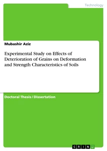
Similar texts


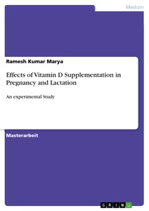

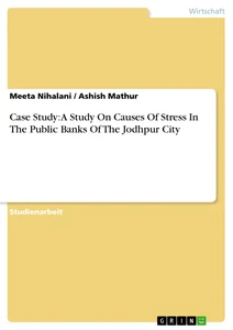


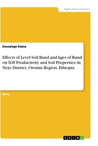


Publish now - it's free

Comments